BIM Modeling for Oil and Gas Facilities
Oil and gas facilities operate highly complex industrial environments where pipelines, processing equipment, structural platforms, and storage systems are tightly integrated. Refineries, compressor stations, offshore platforms, and gas processing plants require precise engineering documentation to support modernization and operational planning.
BIM modeling for oil and gas facilities provides a structured digital representation of plant infrastructure. These models allow engineers to visualize equipment layouts, pipeline routing, and structural systems within a coordinated engineering environment.
Contact Us Now for a Free Consultation!
Companies implementing BIM modeling services for oil and gas facilities gain accurate digital models that support engineering coordination, retrofit planning, and facility modernization.
Role of BIM Modeling in Oil and Gas Engineering
Engineering projects in oil and gas facilities involve multiple disciplines including mechanical, structural, piping, and electrical systems. Without coordinated models, conflicts between these systems may only appear during installation.
BIM models allow engineering teams to analyze plant infrastructure in a unified digital environment. Refineries, pipeline systems, and offshore platforms can be evaluated before construction or equipment upgrades begin.
Using coordinated BIM models improves engineering collaboration and reduces design risks in large industrial facilities.
Industrial Systems Modeled in Oil and Gas BIM Projects
Oil and gas BIM projects typically include several major categories of plant infrastructure.
Process Equipment
Industrial equipment forms the core of oil and gas facilities.
Typical modeled assets include:
- compressors
- separators
- distillation columns
- heat exchangers
These elements must be represented accurately to support engineering coordination and modernization planning.
Pipeline Infrastructure
Pipeline systems connect production units and transport fluids between plant areas.
Typical components modeled include:
- pipeline routing
- pipe racks
- valves and flanges
- pipe supports
Accurate pipeline BIM modeling allows engineers to verify installation clearances and detect potential clashes with surrounding equipment.
Structural Platforms
Industrial plants include structural systems designed to support heavy equipment and piping networks.
These elements typically include:
- steel platforms
- maintenance walkways
- equipment support structures
Structural modeling helps engineers evaluate load paths and coordinate equipment installation.
Storage Infrastructure
Oil and gas facilities often contain large storage and loading areas.
Typical modeled components include:
- storage tanks
- pump stations
- loading systems
These systems must be integrated into the BIM environment to ensure accurate facility documentation.
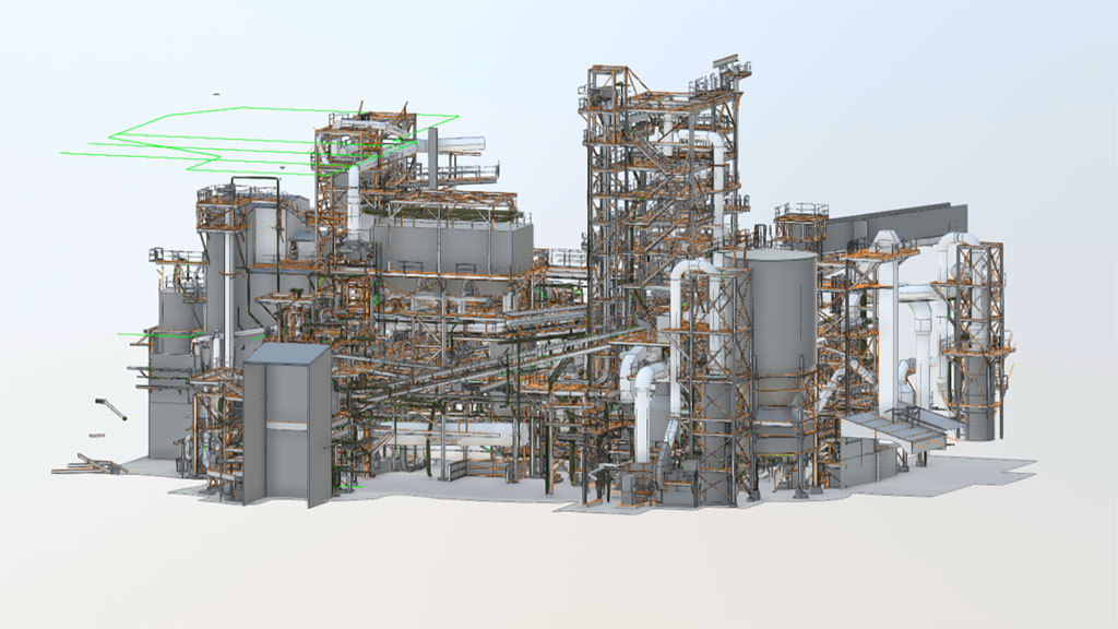
Examples of BIM models for industrial facilities and complex engineering infrastructure
BIM Model for Oil Facility Example


Explore More Industrial BIM Projects
View additional examples of BIM models and digital engineering projects developed for industrial facilities.
Engineering Coordination with BIM Models
One of the primary benefits of BIM modeling is improved engineering coordination.
Industrial facilities contain dense infrastructure where multiple systems intersect. Pipeline networks, equipment foundations, structural platforms, and electrical systems must be integrated without spatial conflicts.
Using BIM models allows engineers to perform clash detection and spatial analysis before installation begins. This helps reduce construction risks and avoid costly field modifications.
Accurate equipment layout BIM modeling also allows engineers to verify maintenance access zones and operational clearances within complex plant environments.
Levels of Detail in Oil and Gas BIM Modeling
Industrial BIM models are typically developed at different levels of detail depending on project requirements.
| BIM Level | Typical Application |
|---|---|
| LOD 200 | Conceptual facility layouts and early engineering studies |
| LOD 300 | Engineering coordination and design verification |
| LOD 350 | System integration and clash detection |
| LOD 400 | Fabrication and installation planning |
For most oil and gas projects, LOD 300–LOD 400 BIM modeling provides sufficient detail for engineering coordination and equipment installation planning.
Applications of BIM Modeling in Oil and Gas Facilities
BIM models are widely used in various engineering scenarios within oil and gas facilities.
Refinery Modernization
Refineries frequently undergo modernization to improve production efficiency or replace aging equipment. BIM models allow engineers to evaluate spatial constraints before implementing design changes.
Pipeline Infrastructure Upgrades
Pipeline systems are often modified during process upgrades. Accurate models help engineers analyze pipe routing and avoid conflicts with existing equipment.
Offshore Platform Retrofits
Offshore installations have strict spatial limitations. BIM models provide reliable geometry for planning equipment upgrades and infrastructure modifications.
Equipment Replacement Planning
Replacing compressors, pumps, or heat exchangers requires precise alignment with existing infrastructure. BIM models help engineers verify installation conditions before construction.
Plant Documentation
Many facilities develop digital plant documentation using BIM models to maintain accurate records of infrastructure and equipment.
Integration with Digital Engineering Workflows
BIM models are often integrated with other digital engineering technologies used in industrial projects.
Reality capture technologies such as 3D Laser Scanning generate accurate spatial datasets of plant infrastructure. These datasets can be converted through Scan to BIM workflows and further processed using Point Cloud Processing tools.
The resulting models can support engineering coordination, asset management, and digital twin development within oil and gas facilities.
Benefits of BIM Modeling for Oil and Gas Operators
Implementing BIM modeling workflows provides several advantages for oil and gas operators.
Key benefits include:
- improved engineering coordination
- reduced design conflicts
- faster modernization planning
- accurate digital plant documentation
- improved collaboration between engineering teams
These advantages help companies manage complex industrial facilities more efficiently.
Typical BIM Modeling Applications in Oil and Gas Facilities
| Facility Type | BIM Modeling Application |
|---|---|
| Oil refineries | coordination of equipment installations |
| Pipeline stations | verification of pipeline routing |
| Offshore platforms | spatial coordination of infrastructure |
| Gas processing plants | equipment layout analysis |
| Storage terminals | facility documentation and planning |
These applications demonstrate how BIM modeling supports engineering decision-making across different oil and gas infrastructure projects.