Scan to BIM for Steel Plants

Modern steel plants consist of large-scale mechanical systems, dense pipe networks, heavy structural frames, and continuously modified production equipment. Accurate digital documentation of these facilities is often incomplete or outdated due to decades of upgrades and retrofits.
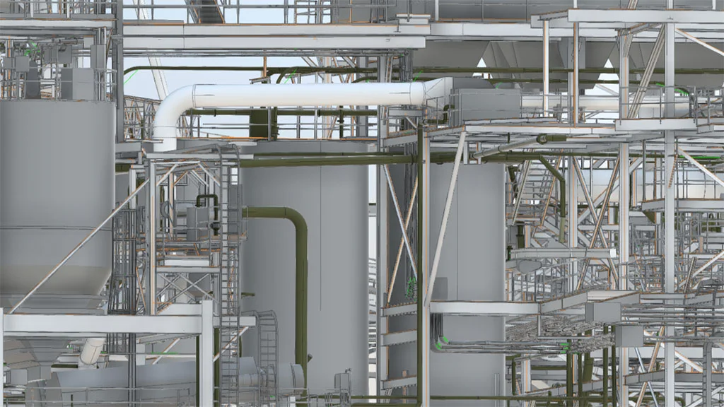
Scan to BIM steel plant workflows convert high-resolution laser scan data into engineering-grade BIM models representing structural systems, equipment geometry, and plant infrastructure. This process transforms point cloud datasets into coordinated digital plant models used for modernization, expansion, and technical audits.
Contact Us Now for a Free Consultation!
Unlike typical industrial facilities, metallurgical plants include unique structures such as blast furnaces, sinter plants, coke ovens, and rolling mill lines. Their geometry is highly irregular due to thermal deformation, accumulated repairs, and layered installations over time. Laser scanning combined with BIM modeling enables engineers to reconstruct the actual plant state with millimeter-level spatial accuracy.
The resulting models support engineering tasks such as equipment replacement planning, structural analysis, layout redesign, and integration of new production lines.
Why Steel Plants Require Scan-to-BIM Reconstruction
Steel production facilities evolve continuously. Equipment is replaced, ductwork is rerouted, platforms are added, and structural reinforcements appear without systematic updates to engineering documentation.
This creates several operational problems.
Incomplete as-built documentation
Many metallurgical plants operate with drawings that represent original construction rather than the current configuration.
Dense mechanical environments
Steel plants contain:
- heavy conveyors
- cooling water pipelines
- gas ducts
- cable trays
- structural supports
Traditional manual measurement methods cannot capture this density reliably.
Limited accessibility
Areas near blast furnaces, ladle furnaces, and continuous casting lines are difficult or unsafe to measure manually due to:
- heat exposure
- vibration
- limited access platforms
Retrofit and modernization planning
Engineering teams require accurate spatial data before installing new equipment or expanding production lines.
Laser scanning eliminates manual measurement errors and provides a complete spatial dataset that can be transformed into a coordinated BIM model.
Typical Workflow for Scan to BIM Steel Production Facilities
The transformation of point cloud data into a BIM environment follows a structured engineering workflow.
1. Laser scanning of production areas
High-precision terrestrial laser scanners capture the geometry of plant infrastructure and equipment.
Typical scanned areas include:
- blast furnace structures
- rolling mill frames
- coke oven batteries
- gas duct networks
- pipe racks and service corridors
- steel structures and platforms
Scanning produces a dense point cloud dataset representing the entire plant geometry.
If the project requires additional survey precision, scanning is combined with geodetic control networks.
2. Point cloud registration and cleaning
Raw scans must be processed before modeling begins.
Processing steps include:
- registration of multiple scan stations
- removal of noise and moving objects
- alignment to plant coordinate systems
- segmentation of structural and mechanical elements
The cleaned dataset becomes a unified point cloud environment used for modeling.
3. BIM modeling of plant structures and equipment
Engineers reconstruct the facility geometry using BIM software platforms .
Typical modeled elements include:
Structural systems
- steel frames
- columns and trusses
- maintenance platforms
- stair towers and access structures
Process equipment
- blast furnace shells
- dust collectors
- rolling mill housings
- conveyor systems
- material bunkers
Piping and duct networks
- gas pipelines
- cooling water lines
- exhaust ducts
- compressed air systems
Electrical and service infrastructure
- cable trays
- equipment foundations
- maintenance walkways
The resulting steel plant BIM modeling services deliver coordinated digital models suitable for engineering workflows.
Technical Elements Specific to Steel Plants
Metallurgical plants include several infrastructure elements rarely present in other industrial facilities. Modeling these components requires specific experience with steel production environments.
Blast furnace systems
Blast furnaces are among the most complex industrial structures. A digital model must capture:
- furnace shell geometry
- tuyere platforms
- hot blast piping
- gas off-take ducts
- charging equipment
Even small spatial deviations influence maintenance and upgrade planning.
Continuous casting equipment
Continuous casting lines contain large mechanical frames and moving assemblies.
Key elements typically modeled include:
- mold support structures
- strand guides
- tundish platforms
- maintenance rails
- secondary cooling pipe systems
These components require precise alignment with existing foundations.
Gas cleaning and duct infrastructure
Steel plants rely on extensive gas handling systems for furnace operation and emission control.
Modeling tasks may include:
- large-diameter ducts
- cyclones and dust collectors
- exhaust stacks
- filtration systems
These systems often intersect with structural frames and pipe racks, making spatial coordination critical.
Deliverables Produced from Steel Plant Scan-to-BIM Projects
Engineering teams typically require several outputs from the modeling process.
BIM model of the metallurgical facility
The primary deliverable is a coordinated BIM model representing:
- structural steel systems
- mechanical equipment
- piping infrastructure
- access platforms
The model can be delivered in common formats such as:
- Revit
- IFC
- Navisworks
Engineering drawings and documentation
From the BIM model, engineers can extract:
- equipment layout drawings
- piping routing diagrams
- structural plans
- maintenance platform layouts
Clash detection and coordination models
When new equipment is installed inside existing production halls, the BIM environment enables clash detection between:
- new machinery
- structural frames
- existing pipe networks
This reduces installation conflicts and construction delays.
Digital plant models for modernization planning
The BIM model may also serve as the foundation for a steel plant digital twin modeling environment used for:
- asset management
- maintenance planning
- expansion design
Applications of BIM Models in Steel Production Facilities
Once generated, digital models become part of several engineering workflows.
Equipment replacement projects
When replacing rolling mill stands or furnace components, engineers must verify:
- structural clearances
- equipment transport paths
- foundation alignment
BIM models provide this spatial validation.
Plant expansion and layout redesign
Steel plants frequently install additional processing lines such as:
- billet casting
- hot rolling lines
- cooling beds
Accurate digital plant geometry allows engineers to simulate installation scenarios before construction begins.
Structural integrity assessments
Heavy equipment loads and thermal stress affect structural elements over time.
The BIM model allows engineers to analyze:
- beam deformation
- platform stability
- support structure loading
Safety and maintenance planning
Maintenance routes and access platforms can be verified using the digital model.
Typical planning tasks include:
- crane access paths
- maintenance platform positioning
- equipment clearance zones
Key Advantages of Scan-to-BIM for Steel Mills
The engineering benefits of digital reconstruction are substantial.
Accurate plant geometry
Laser scanning captures real-world geometry with millimeter-level accuracy.
Reduced engineering uncertainty
Design teams can plan upgrades using actual plant conditions instead of outdated drawings.
Improved installation planning
Clash detection prevents conflicts during equipment installation.
Faster modernization projects
Engineering teams work with reliable spatial data from the beginning of the project.
Comparison of Traditional Documentation vs Scan-to-BIM
| Aspect | Traditional Measurement | Scan-to-BIM |
| Measurement accuracy | Limited, manual errors possible | Millimeter-level accuracy |
| Data coverage | Selected points only | Full spatial environment |
| Time required | Long field measurements | Rapid scanning |
| Documentation completeness | Often incomplete | Comprehensive digital model |
| Retrofit planning | High uncertainty | Reliable spatial validation |
Data Accuracy and Modeling Levels
Steel plant BIM models are typically delivered with different levels of detail depending on the project scope.
| Level | Typical Use |
| LOD 200 | Layout planning |
| LOD 300 | Engineering coordination |
| LOD 350 | Equipment installation planning |
| LOD 400 | Fabrication-ready modeling |
For metallurgical plants, LOD 300–350 is commonly required due to the complexity of equipment layouts.
Challenges in Modeling Steel Production Facilities
Despite the benefits, Scan-to-BIM projects for steel plants present several technical challenges.
High structural density
Production halls often contain overlapping:
- pipe racks
- structural beams
- ducts
- cable trays
Segmenting these elements from point cloud data requires specialized workflows.
Surface reflectivity
Steel surfaces and hot equipment may create scan noise and reflections.
Additional scan positions are often required to capture accurate geometry.
Thermal deformation
Blast furnace and casting structures may have slight geometric distortions due to long-term heat exposure.
Modeling must represent the actual measured geometry, not theoretical design shapes.
Future Role of BIM in Metallurgical Facilities
Digital plant modeling is becoming a standard engineering practice in heavy industry.
For steel production facilities, BIM models enable:
- predictive maintenance planning
- digital twin integration
- lifecycle asset management
- simulation of plant upgrades
As more metallurgical companies adopt digital engineering platforms, scan-to-BIM reconstruction will play a central role in creating accurate digital plant environments.