

Scan to BIM for Manufacturing Facilities
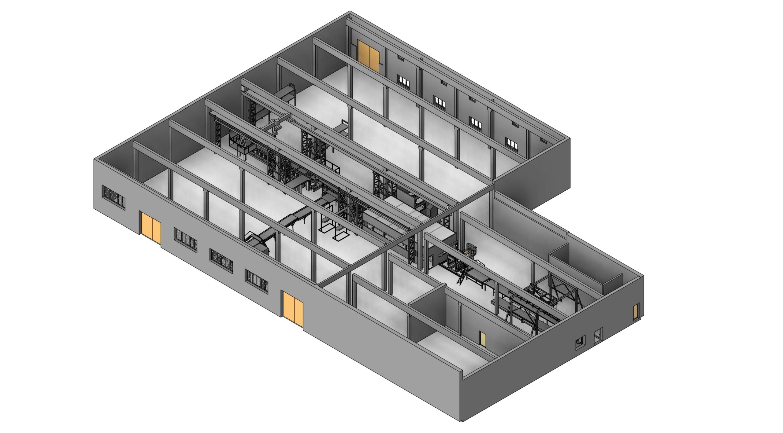
Manufacturing facilities require precise spatial documentation to maintain operational efficiency, support upgrades, and ensure compliance with engineering standards. Traditional drawings often fail to reflect current site conditions due to continuous equipment changes, retrofits, and layout adjustments.
Scan to BIM for manufacturing facilities provides a reliable method to capture existing conditions and convert them into accurate digital models. Using laser scanning and point cloud data, this process enables engineers and facility managers to work with up-to-date, geometry-rich BIM models tailored specifically for production environments.
Scan to BIM services for manufacturing facilities are widely used by engineering companies, industrial operators, and contractors to support modernization, expansion, and digital transformation of production environments. Accurate BIM models enable better coordination between equipment, structures, and engineering systems while reducing risks during industrial projects.
Contact Us Now for a Free Consultation!
Scope of Scan to BIM for Manufacturing Facilities
Scan to BIM in factories and production plants focuses on capturing and modeling elements that directly impact manufacturing operations. Unlike commercial or residential buildings, manufacturing environments involve dense equipment layouts, process-specific installations, and utility networks that must be modeled with high precision.
Typical deliverables include:
- Factory layout BIM models with equipment positioning
- Production line digital models
- Structural and architectural components of industrial workshops
- MEP systems adapted to manufacturing processes
- Equipment foundations and anchoring systems
- Overhead crane systems and rail alignments
- Pipe racks and compressed air distribution networks
This approach ensures that the resulting BIM model reflects the real operational state of the facility rather than outdated design intent.
Data Acquisition: Laser Scanning and Point Cloud Processing
The process begins with high-resolution 3D laser scanning of the manufacturing facility. This stage captures millions of spatial data points representing surfaces, equipment, and infrastructure.
Relevant services:
Key considerations during scanning:
- Minimizing production downtime during data capture
- Capturing congested zones such as production lines and machinery clusters
- Ensuring sufficient coverage of elevated systems (ducts, conveyors, cable trays)
- Maintaining accuracy in areas with repetitive geometry (e.g., assembly lines)
The output is a registered point cloud dataset, which serves as the foundation for BIM modeling.
Manufacturing Facility BIM Models


BIM Modeling for Manufacturing Facilities
Once the point cloud is processed, it is converted into a structured BIM model. Unlike generic BIM workflows, modeling for manufacturing facilities requires selective detailing based on operational relevance.
Modeling Priorities
- Production Equipment Integration
Equipment such as CNC machines, conveyors, robotic arms, and assembly stations must be accurately positioned. Clearance zones, maintenance access, and safety buffers are included. - Process-Oriented Layouts
The BIM model reflects actual production flow rather than architectural zoning. This includes material handling paths and workflow alignment. - Utility Systems Specific to Manufacturing
- Compressed air lines
- Process cooling systems
- Industrial ventilation and extraction systems
- Structural Adaptations
Reinforced slabs, machine foundations, and vibration isolation elements are modeled where relevant.
Industry-Specific Technical Elements
Scan to BIM for manufacturing facilities involves several technical aspects not typically present in other sectors:
1. Production Line Alignment
Accurate positioning of sequential machinery is critical. Even minor deviations can impact automation systems and material flow. BIM models must reflect true alignment and spacing.
2. Overhead Transport Systems
Many factories use overhead cranes, monorails, or conveyor systems. These require precise modeling of rails, supports, and clearance envelopes.
3. Process Piping and Utility Networks
Unlike standard MEP systems, manufacturing plants often include:
- High-pressure compressed air systems
- Process-specific piping (coolants, lubricants, gases)
- Dedicated exhaust and filtration systems
These systems must be modeled with correct routing and connectivity to support engineering analysis.
Applications of Scan to BIM in Manufacturing
Facility modernization and Retrofit Planning
Manufacturing plants frequently undergo upgrades. Scan to BIM provides an accurate baseline for integrating new equipment without clashes.
Factory Layout Optimization
Digital models allow engineers to analyze and improve production flow, reduce bottlenecks, and optimize space utilization.
Equipment Relocation and Installation
Precise BIM models support planning for relocating machinery or installing new production lines, ensuring compatibility with existing infrastructure.
Maintenance and Asset Management
BIM models serve as a reference for maintenance teams, enabling faster identification of systems and components.
Safety and Compliance
Accurate digital models help verify compliance with safety regulations, including clearance zones, escape routes, and equipment spacing.
Accuracy and Level of Detail
For manufacturing facilities, accuracy requirements are typically higher than in standard building projects due to equipment sensitivity.
- Typical accuracy: ±3–5 mm depending on project scope
- Level of Detail (LOD):
- LOD 300 for general layouts
- LOD 350–400 for equipment and critical systems
Modeling is tailored to project goals, avoiding unnecessary detail that does not contribute to engineering outcomes.
Challenges in Manufacturing Scan to BIM
Dense and Complex Environments
Production areas often contain tightly packed equipment, making scanning and modeling more complex.
Continuous Operation
Facilities may operate 24/7, limiting access for scanning. This requires phased or off-hours data capture strategies.
Frequent Changes
Manufacturing environments evolve rapidly. Models must reflect current conditions rather than historical layouts.
Equipment Diversity
Different types of machinery require custom modeling approaches rather than standardized BIM components.
Benefits of Scan to BIM for Manufacturing Facilities
Scan to BIM provides measurable advantages for manufacturing facilities, engineering companies, and industrial operators working with complex production environments.
Accurate Representation of Existing Conditions
Laser scanning and BIM modeling create a precise digital replica of the facility, reflecting actual equipment placement, structural elements, and utility systems rather than outdated drawings.
Reduced Risk During modernization and Equipment Installation
Accurate spatial data minimizes the risk of clashes, misalignment, and installation errors when integrating new machinery or upgrading production lines.
Improved Coordination Between Engineering Teams
BIM models enable collaboration between mechanical, structural, and MEP engineers, ensuring consistent data across all disciplines.
Enhanced Decision-Making Through Digital Visualization
Engineers and facility managers can analyze layouts, simulate changes, and evaluate multiple scenarios before implementation.
Optimized Production Workflows and Space Utilization
Digital models help identify bottlenecks, improve material flow, and optimize equipment placement within production areas.
Reduced Downtime During Reconstruction and Modernization Projects
Accurate planning based on real conditions reduces unexpected issues and minimizes disruption to ongoing production.
Workflow Overview
- Site assessment and scanning strategy development
- 3D laser scanning and data capture
- Point cloud registration and cleaning
- Conversion to BIM model
- Quality control and validation
- Delivery in required formats (Revit, IFC, Navisworks, etc.)
Each stage is adapted to the specific requirements of manufacturing operations.
Conclusion
Scan to BIM for manufacturing facilities provides a precise and practical solution for documenting and managing industrial environments. By converting real-world conditions into structured BIM models, it supports engineering workflows, improves operational planning, and reduces risks associated with facility modifications.
Unlike generic BIM applications, this approach is tailored to the realities of production plants, where equipment alignment, utility systems, and process flows define the success of any project.

