
Piping & Process Plant 3D Modeling from Laser Scans
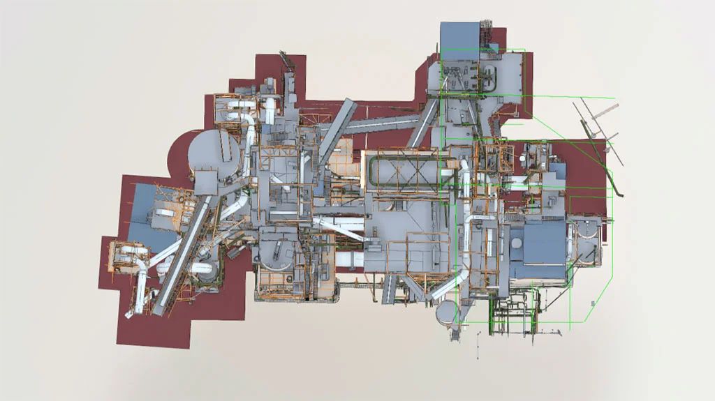
Most process plants are not built once. Lines are rerouted, equipment is replaced, supports are added during shutdowns, and the drawings rarely keep up. When the next revamp, tie-in or equipment change comes, engineers need to know where the pipes really are. ScanM2 builds as-built 3D models of piping, equipment, supports and structural steel from 3D laser scans of your plant, so your design and construction teams start from the facility as it exists today, not as it was drawn years ago.
Contact Us Now for a Free Consultation!
Our work is the model of what exists. We capture and model existing piping systems and the plant around them; the new design, the engineering calculations and the fabrication documents stay with your engineers or your EPC contractor, who receive a reliable base to work from.
Why Plants Need a Model Built From a Scan
Measuring a pipe rack with a tape is slow, risky and incomplete. Old isometrics and plot plans show design intent, not field changes. A laser scan captures the whole area at once: pipe runs at height, congested pipe racks, equipment nozzles, valves, supports and the steel they hang from. Building the 3D model directly on that point cloud means every modeled element can be checked against measured data.
Typical reasons our clients order a piping and plant model:
- Revamps and debottlenecking, where new lines must connect to existing ones.
- Tie-ins, where the exact position and orientation of an existing flange or nozzle matters.
- Equipment replacement, to check space, access routes and connections before the shutdown.
- Clash checks between a new design and the existing plant.
- An up-to-date record of a unit whose drawings no longer match reality.
For a wider look at how plant models are used, read our article on industrial plant modeling using scan to BIM.
What We Model
| Element | What is included |
|---|---|
| Piping | Pipe runs, elbows, tees, reducers, flanges, valves and visible inline items, with nominal size where it can be confirmed |
| Equipment | Vessels, tanks, pumps, compressors, exchangers, skids, with main dimensions and nozzle positions |
| Supports | Shoes, guides, hangers, trunnions and support steel visible in the scan |
| Structural steel | Pipe racks, platforms, stairs, ladders, columns and beams |
| Building and civil | Walls, slabs, foundations and openings around the process area, when required |
| Other services | Cable trays, ducts and fire protection lines, when agreed in the scope |
Before modeling starts, we agree on a minimum pipe size and on how much detail each element type needs. A unit model for a tie-in study may need every small-bore line near the connection; a model for layout studies may keep only main lines and equipment envelopes. Equipment can be modeled as simplified shapes or as detailed Revit families with connectors, see our Revit family creation services.
How We Work
- Scope review. You send the area boundaries, existing drawings and what the model will be used for. We propose the minimum pipe size, the level of detail and the deliverables.
- Laser scanning. We scan the plant with FARO laser scanners, working within your site safety rules and permits. Typical accuracy of the registered point cloud is ±2–3 mm. We travel to sites in any US state, or we model from a point cloud your team or your scanning provider has already captured.
- Modeling on the point cloud. Pipes, equipment and steel are modeled directly on the scan in Autodesk Revit or AutoCAD. Line data from your documents is added as parameters.
- Model check. We compare the finished model with the point cloud and review connections, sizes and elements that are hard to see.
- Delivery and review. You receive the model, the point cloud and the list of open items, and we answer your team’s questions.
More about the capture side in our 3D laser scanning services.
Insulation, Hidden Lines and Line Data
Three questions decide whether a piping model can be trusted, and we settle them with you in advance.
Insulation. A scanner sees the outside of the insulation, not the pipe. For insulated lines we model the nominal pipe size from your line list or specification and, if needed, show the insulation thickness separately. Where no documents exist, we mark the size as estimated.
Hidden and unreachable lines. Pipes inside walls, under grating, in trenches or behind equipment may not appear in the scan. We do not invent them. Such elements are either left out or modeled from your drawings and marked as “from documents”.
Line numbers and data. Line number, service, size and specification can be added to the model as Revit parameters when you provide P&IDs or a line list. Every element carries a status parameter: verified by scan, taken from documents, or assumed.
What We Do Not Do
We want the boundaries of this service to be clear from the first conversation:
- No pipe stress analysis or hydraulic calculations.
- No spool or fabrication isometrics.
- No P&ID development or process design.
- No engineering stamps or sealed drawings.
These tasks belong to your engineers or engineering contractor. Our model gives them an accurate picture of the existing plant to design, check and prepare fabrication documents against.
Clash Checks Against the Existing Plant
When a new design is being developed, the as-built model can be combined with it in Navisworks. Clash detection between new lines and existing pipes, steel and equipment shows conflicts before material is ordered and before the shutdown starts. We can run the clash check and deliver a report with views of each conflict, or hand over the models for your team to check. See our BIM clash detection services.
What You Receive
| Deliverable | Details |
|---|---|
| 3D model | Native Revit (RVT) or AutoCAD (DWG), in your version and template |
| .ifc export | For exchange with other BIM and plant software. See IFC file format explained |
| Navisworks file | Model and point cloud combined for review and clash checks |
| Point cloud | Registered scan data in a common format, linked to the model |
| Drawings | Plans, sections and elevations of the modeled areas as DWG or PDF on request |
| Open items list | Elements that could not be verified, estimated sizes and missing documents |
Industries We Work For
- Oil and gas production and processing facilities. See our BIM solutions for the oil and gas industry and oil and gas production BIM modeling.
- Chemical plants and process units.
- Manufacturing plants with process piping, utilities and compressed air systems.
- Boiler houses and utility plants.
- Food, beverage and pharmaceutical production with stainless process lines.
What We Need From You
- Area boundaries on a plot plan, and the purpose of the model.
- Existing P&IDs, line lists, piping specifications and equipment lists, where available.
- Insulation specification or thickness table for insulated lines.
- Site access, safety requirements and permits for the scanning crew, or your existing point cloud.
- Your Revit or CAD template and naming rules, if you have them.
If some documents are missing, we still deliver the geometry visible in the scan and list what remains open.
FAQ
What are piping 3D modeling services from laser scans?
How accurate is a piping model built from a laser scan?
What is the smallest pipe size you model?
How do you model insulated pipes?
Can you add line numbers and other data to the model?
Do you provide stress analysis or fabrication isometrics?
Which file formats do you deliver?
Can you scan our plant or work from our existing point cloud?
Send Us Your Project
Tell us which plant and areas you need, what the model will be used for and which documents you already have: drawings, P&IDs, line lists or a point cloud. We review the information, propose the scope and level of detail, and send a quote based on it.

