
Point Cloud to Mesh: Methods, Cleanup and When to Use a Mesh
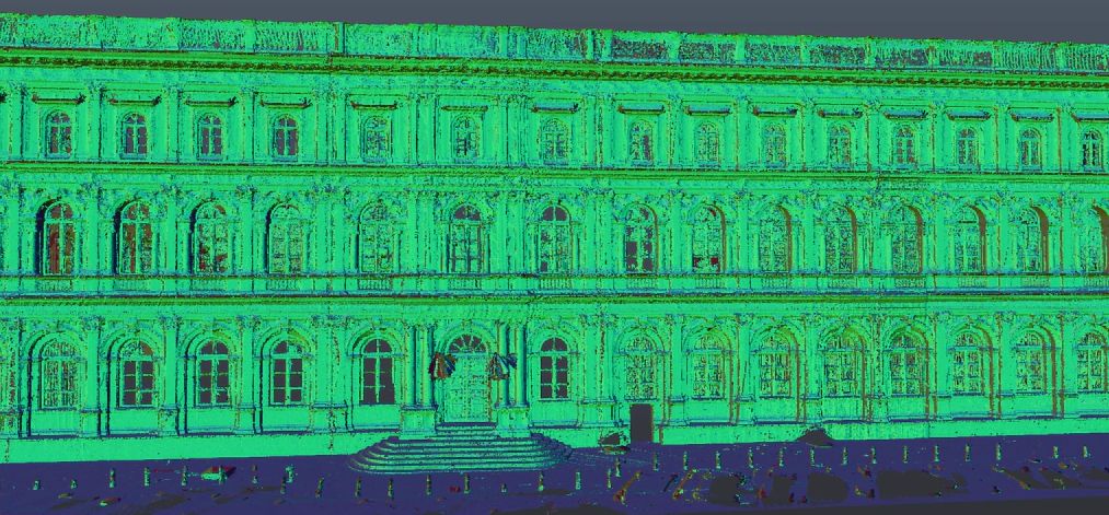

A laser scanner does not capture surfaces. It captures points: millions of separate measurements, each with a position and often a color and intensity value. Between those points there is nothing. To get a continuous surface that can be 3D printed, rendered, shared as a lightweight file or used as the base for reverse engineering, the point cloud has to be turned into a mesh.
This article explains what a mesh is, how point cloud to mesh conversion works, which steps decide the quality of the result, which file formats are used, and when a mesh is the right deliverable instead of a CAD drawing or a BIM model.
What Is a Mesh?
A mesh is a surface made of small flat faces, almost always triangles. Each triangle connects three vertices, and neighboring triangles share edges. Together they form a continuous skin that follows the shape of the scanned object.
The difference from a point cloud is simple:
- A point cloud is a set of separate samples. You can see the object in it, but it has no surfaces, so it cannot be printed, measured as an area or volume, or textured as one object.
- A mesh connects those samples into faces. It has surfaces, normals that show which side is “outside”, and, if it is closed, a volume.
The difference from a CAD or BIM model matters just as much. A mesh describes shape only. It does not know that a group of triangles is a wall, a pipe or a bolt hole, and it has no parameters such as thickness, diameter or material. It is a very detailed digital copy of a surface, not an engineering model.
How Point Cloud to Mesh Conversion Works
Converting a point cloud to a mesh is not a single button. The result depends far more on preparation than on the meshing command itself. A typical workflow has five steps.
Step 1: Register and Check
Most objects need several scan positions. Before meshing, all scans are joined into one point cloud. If two scans are misaligned, the mesh will show it as doubled surfaces, steps or ridges along the joint. Registration is checked on section cuts and overlap areas before any surface is built. We explain this stage in how point cloud registration works.
Step 2: Clean
Every scan contains points that do not belong to the object: people walking by, reflections from glass and polished metal, mixed points along edges, dust, vegetation, tripods and stray points in the air. A meshing algorithm treats every point as part of a surface, so each of these becomes a lump, spike or false wall. Cleaning removes them and, where needed, reduces noise on surfaces. The process is described in more detail in our article on point cloud cleaning.
Step 3: Estimate and Orient Normals
A normal is a direction that shows which way a surface faces. Many meshing methods need a normal for every point to know which side is inside and which is outside. Normals are estimated from neighboring points, and their orientation is checked. If part of the normals point inward, the mesh can come out inside-out or broken in that area. Data from terrestrial scanners has an advantage here: each scan position is known, so normals can be oriented toward the scanner.
Step 4: Build the Surface
This is the meshing itself. The main methods are compared in the table below.
Step 5: Edit, Reduce and Check
The raw mesh is then repaired, simplified to a usable size, filled where required and compared with the original point cloud. These steps are covered in the sections that follow.
Meshing Methods Compared
Different algorithms suit different data. The names vary between programs, but most tools offer some version of these four.
| Method | How it works | Best for | Watch out for |
|---|---|---|---|
| Direct triangulation | Connects neighboring points into triangles; the surface passes through the measured points | Dense, clean scans of objects where every detail should stay | Keeps noise; leaves holes where data is missing |
| Poisson reconstruction | Fits a smooth, closed surface to the points using their normals | Organic and sculpted shapes, heritage objects, closed models for printing | Can invent surface across gaps; sharp edges get rounded; needs good normals |
| Voxel or fusion methods | Divides space into small cubes and builds the surface from them | Noisy or uneven data, quick previews, large scenes | Detail is limited by voxel size; fine edges soften |
| Alpha shape and similar | Connects points within a set radius; the radius decides how big a gap is closed | Simple objects and quick envelopes | Wrong radius either leaves holes or closes real openings |
For engineering work, a common choice is direct triangulation on a well-cleaned cloud, because the surface stays on the measured points. For sculpture, ornament and objects that must be printed, Poisson reconstruction often gives a better looking, closed result, but every area where it filled a gap should be known and checked.
Decimation: Making the Mesh Usable
A mesh built from a dense laser scan can contain tens of millions of triangles. That is often more than a viewer, a game engine, a slicer for 3D printing or a modeling program can handle comfortably.
Decimation reduces the number of triangles while keeping the shape. Good decimation is adaptive: it removes many triangles on flat areas, where they add nothing, and keeps them on edges, curves and fine detail. The key setting is the allowed deviation from the original surface, not a percentage. A mesh reduced to a small fraction of its triangles can still follow the scan closely if the simplification was controlled.
Two practical rules:
- Keep the full-resolution mesh as the master and create lighter versions for each use: one for web viewing, one for rendering, one for printing.
- Agree on the target file size or triangle count with whoever will use the mesh before delivery.
Holes, Watertight Meshes and Repair
A scanner records only what it can see. Undersides, deep recesses, areas behind other objects and very dark or shiny surfaces often leave gaps. A mesh built from such data has holes.
A watertight mesh is one with no holes: a fully closed surface that separates inside from outside. It is also manifold, meaning every edge is shared by exactly two triangles, with no stray faces, self-intersections or flipped normals. Watertight meshes are needed for:
- 3D printing, because the slicer has to know what is solid;
- volume calculations;
- some simulation and analysis tasks.
For visualization and many measurement tasks, a mesh does not have to be watertight.
Hole filling is useful, but it is an assumption, not a measurement. A filled patch shows a plausible surface where no data exists. On a heritage object or a part for reverse engineering, it is good practice to mark filled areas, or deliver them as a separate layer, so nobody later measures a surface that was never scanned.
Typical repair tasks also include removing small floating pieces, fixing flipped normals, smoothing noise without losing edges and splitting the mesh into logical parts.
Color and Texture
Laser scans often carry color from the scanner’s camera. On a mesh, that color can be stored in two ways:
- Vertex color: each vertex has a color. Simple, but the color detail drops when the mesh is decimated.
- Texture: an image is wrapped onto the mesh through a UV map. The geometry can be light while the surface still looks detailed. This is the usual choice for visualization and heritage presentation.
Mesh File Formats
The format should match where the mesh is going. These are the most common ones.
| Format | Stores | Typical use |
|---|---|---|
| OBJ | Geometry, UV coordinates; textures through a separate material file | Visualization, exchange between 3D programs, textured heritage models |
| STL | Triangles only, no color or units | 3D printing, many CAD and manufacturing tools |
| PLY | Geometry with per-vertex color and other attributes | Scan data exchange, archiving colored meshes |
| FBX | Geometry, materials, textures, scene data | Animation, game engines, visualization |
| glTF / GLB | Geometry and textures in a compact, web-friendly form | Online viewers, AR and web presentation |
Two things to check with any format: the units (STL in particular does not store them, so a model in meters can arrive a thousand times too small or too large) and the coordinate system, if the mesh has to sit in the same position as other project data.
How to Check a Mesh Against the Scan
A mesh always differs slightly from the point cloud. Triangles are flat, decimation removes detail, smoothing moves surfaces, and hole filling adds surface where there were no points. The question is whether these differences stay within what the project needs.
The usual check is a deviation analysis: the mesh is compared with the original point cloud, and the distance between them is shown as a color map. Areas where the mesh departs from the scan stand out immediately and can be reviewed. The scan itself sets the limit: our FARO laser scans have a typical accuracy of ±2–3 mm, and a mesh cannot be more accurate than the data it was built from.
Mesh vs CAD vs BIM: Which Deliverable Do You Need?
A mesh, a CAD model and a BIM model can all be built from the same scan. They answer different questions.
| Mesh | CAD model | BIM model | |
|---|---|---|---|
| What it is | Triangulated surface that copies the scanned shape | Clean geometry: lines, solids, NURBS surfaces with exact dimensions | Building elements with geometry and information |
| Follows real imperfections | Yes, including wear, damage and deformation | Usually simplified to design intent | Usually simplified to agreed modeling rules |
| Editable as design | Hard: changing a hole size means editing many triangles | Yes, by dimensions and features | Yes, by element type and parameters |
| Carries information | Shape and color only | Dimensions, sometimes features | Element types, materials, parameters, .ifc export |
| Best for | Visualization, heritage records, 3D printing, deviation checks, base for reverse engineering | Manufacturing, drawings, fabrication of replacement parts | Design, renovation, coordination and facility management of buildings |
In many projects the answer is not “one or the other”. A mesh is often an intermediate step: a reverse engineering specialist uses it as the reference for building a parametric CAD model, or a heritage project keeps a detailed mesh of ornament while the building itself is modeled in Revit. If you are deciding between drawings and models, our article on point cloud to CAD explains the CAD route.
When a Mesh Is the Right Choice
Reverse Engineering
For a part with no drawings, a mesh is the first digital copy of its real shape. It is used to measure the part, check wear and deformation, and serve as the reference surface for a CAD model that can be manufactured. Simple prismatic parts are often modeled directly from the cloud; complex freeform parts usually go through a mesh first. See our reverse engineering services for how scanning and modeling work together.
Heritage and Historic Objects
Carved stone, sculpture, moldings, ornament and damaged surfaces are poorly described by straight lines and parametric families. A textured mesh records their real condition: cracks, losses and weathering. It is used for conservation records, condition monitoring, restoration planning and making replicas. Learn more about our heritage scanning services.
Visualization and Presentation
A decimated, textured mesh opens in web viewers, presentation tools and game engines, where a raw point cloud is too heavy or not supported. Meshes from scans are also used as context in renders, for example an existing building next to a proposed design. For finished images and animations, see our CAD rendering services.
3D Printing and Replicas
Printing needs a watertight mesh in a format such as STL. Scale models of buildings, replicas of museum pieces and replacement decorative elements all start this way.
Deviation and Condition Checks
A mesh of the current state can be compared with a design model or with an earlier scan to show deformation, wear or differences between design and reality as a color map.
When a Mesh Is Not the Best Choice
If the goal is to design a renovation, coordinate MEP systems, produce floor plans or manage a building, a mesh is the wrong tool. Designers need walls, doors, floors and pipes as real elements, which means a CAD drawing set or a BIM model. In that case the scan goes to scan to BIM or CAD modeling, and a mesh is used only where unusual shapes need it.
What to Specify When Ordering a Mesh
- Purpose: printing, visualization, reverse engineering, heritage record or comparison.
- Format and units: OBJ, STL, PLY, FBX or glTF; meters, feet or inches.
- Watertight or open: and whether filled areas should be marked.
- Size limit: a target triangle count or file size for each version.
- Color: none, vertex color or texture.
- Coordinate system: local, or matching other project data.
- Which areas matter most, so detail is kept where it is needed.
FAQ
What does point cloud to mesh mean?
Which meshing method is best for laser scans?
What is a watertight mesh?
What is mesh decimation?
Which file format should I use for a mesh?
Can a mesh be used instead of a CAD or BIM model?
How accurate is a mesh made from a laser scan?
Can you make a mesh from my existing point cloud?
From Points to a Usable Surface
A good mesh starts long before the meshing command: with a well-registered, clean point cloud and a clear purpose. The method, decimation, hole filling and format all follow from what the mesh is for, whether that is a replica, a heritage record, a presentation or the base for a CAD model. ScanM2 travels to sites in any US state for FARO laser scanning and can also work from your existing point cloud, delivering meshes, CAD models and Revit models from the same data. Learn more about our 3D modeling services, or send us your project details to discuss which deliverable fits your task.

ScanM2 Launches ScanTrack: Manage Tasks Directly in a 3D Virtual Tour
18.10.2026
How integrating as-built documentation using advanced 3D scanning and laser scanning technology can revolutionize your real estate marketing strategy. Learn the benefits for agents and ...
Which 3D Laser Scanner Should Architects Choose, and When Is Outsourcing Better?
17.10.2026
How integrating as-built documentation using advanced 3D scanning and laser scanning technology can revolutionize your real estate marketing strategy. Learn the benefits for agents and ...

INTERGEO: How Laser Scanning Is Becoming a Foundation for Management and Decision-Making
24.09.2026
ScanM2 once again took part in INTERGEO, which was held in Munich this year. For us, the event is an opportunity to meet with partners, ...

How 3D Laser Scanning Measures Floor Flatness and Levelness
22.09.2026
Floor flatness and levelness can directly affect equipment installation, racking systems, automated material handling, production lines, flooring systems, and other construction activities that depend on ...

