Architectural documentation of heritage buildings is the process of recording the geometry, structure, visible condition, and key architectural features of historic properties in a form that can support restoration, conservation, renovation, and long-term management. For buildings with cultural, historical, or architectural value, documentation must be more than descriptive. It has to be accurate enough to reflect the real condition of the structure and detailed enough to support future design and preservation decisions.
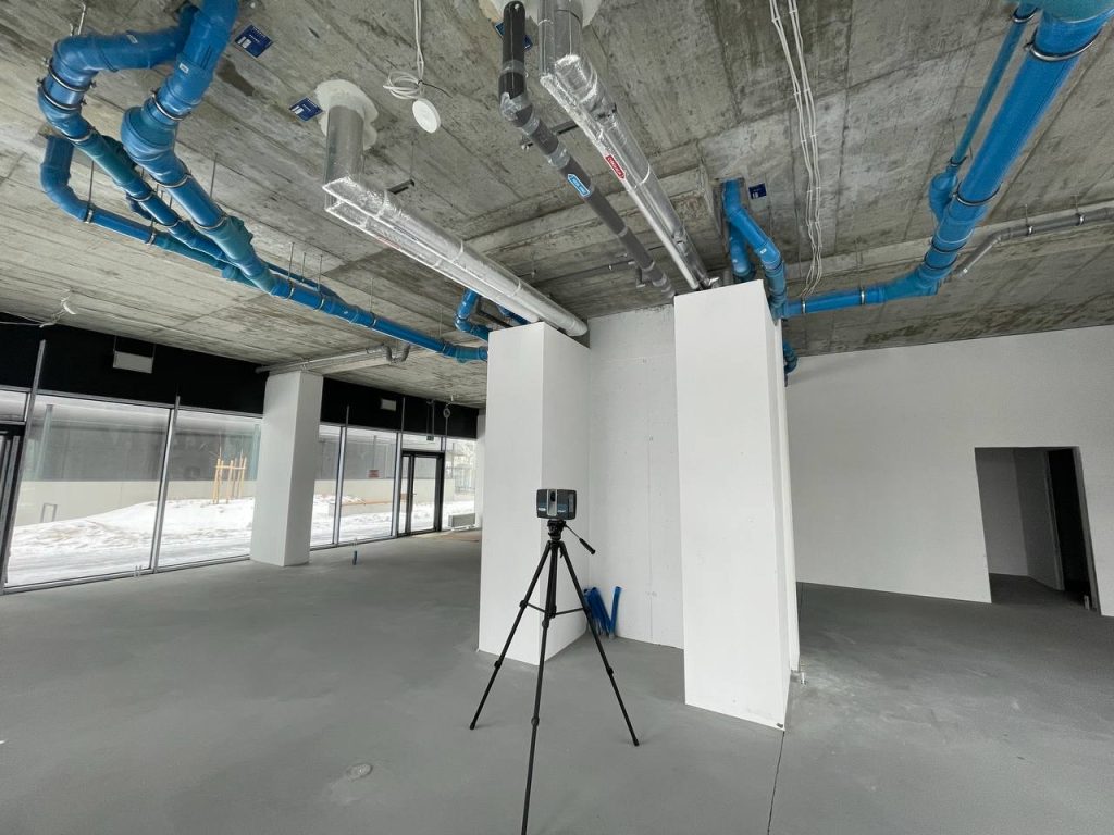
This is where 3D laser scanning services play a major role. Instead of relying only on manual measurement, partial drawings, or fragmented archival records, project teams can work from dense and measurable spatial data. For complex historic properties, this creates a much stronger foundation for heritage documentation, especially when the building contains irregular geometry, deformation, layered construction history, or fine architectural detail.
At ScanM2, this type of work often connects directly with point cloud services, digital existing-conditions workflows, and structured modeling processes that help transform site data into practical documentation deliverables.
What Architectural Documentation Means for Heritage Buildings
In heritage projects, architectural documentation is not simply a set of drawings. It is a precise record of the building as it exists at the time of survey. That may include plans, sections, elevations, facade studies, visible construction logic, deformation patterns, surface irregularities, and details that are important for conservation or restoration planning.
For historic buildings, documentation has to account for realities that are rarely present in new construction:
- walls that are no longer straight,
- uneven floors and settlement-related movement,
- decorative elements with complex geometry,
- later interventions and undocumented changes,
- inconsistencies between archival drawings and the actual building.
Because of this, documentation of historic buildings requires a method that captures real conditions rather than assumed geometry. The more significant the building, the more important that accuracy becomes.
Why Traditional Measurement Is Often Not Enough
Traditional measurement still has its place, but in many heritage projects it becomes too limited when used alone. Manual methods can miss subtle deformations, overlook inaccessible details, and create gaps between surveyed elements and the full spatial logic of the building.
This is especially problematic in projects involving:
- restoration of damaged or altered structures,
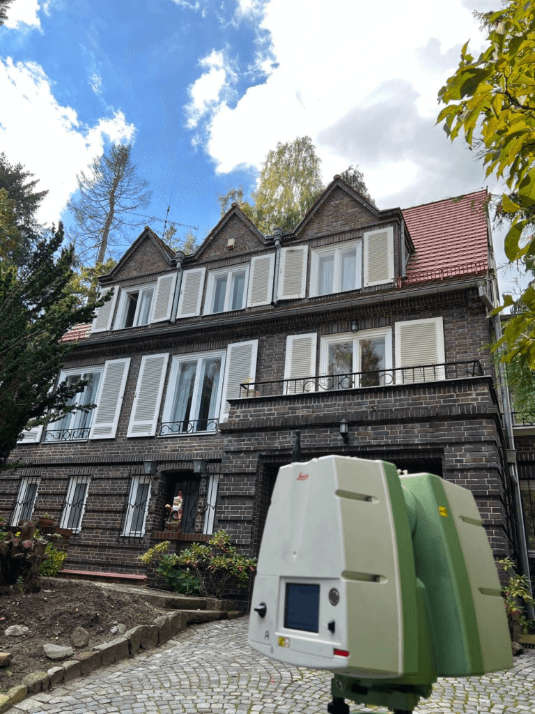
- detailed facade recording,
- adaptive reuse of old buildings,
- conservation of decorative architectural elements,
- preparation of accurate existing-conditions records before design begins.
When the goal is reliable existing conditions documentation for historic buildings, partial measurement is often not enough. Historic structures tend to contain too much geometric variation to be represented accurately through simplified manual capture.
How 3D Laser Scanning Improves Heritage Documentation
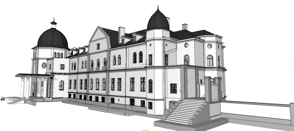
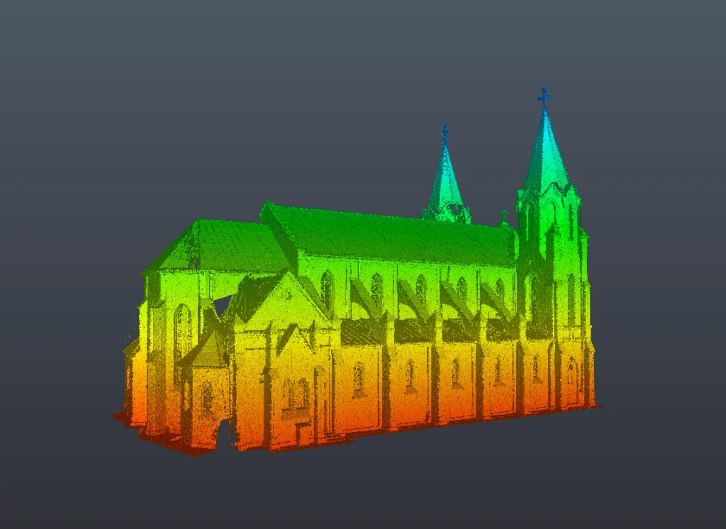
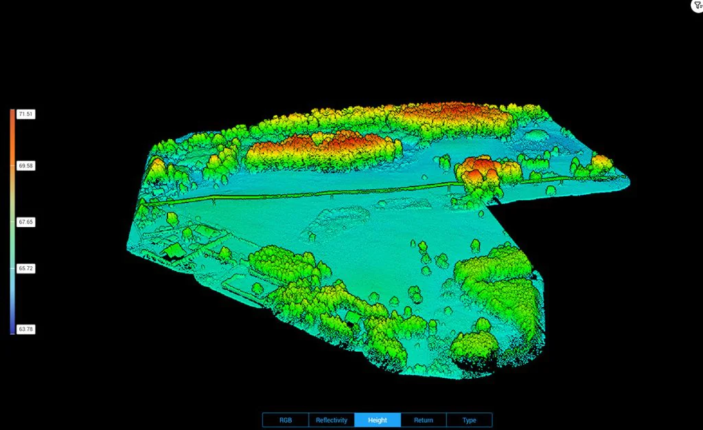
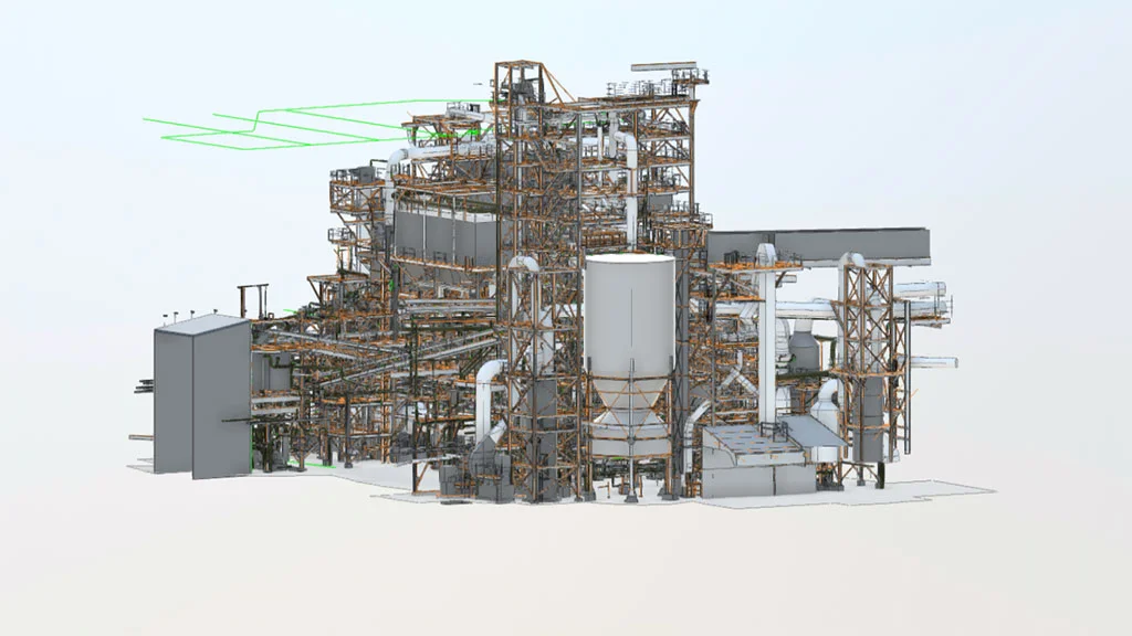
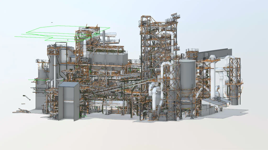
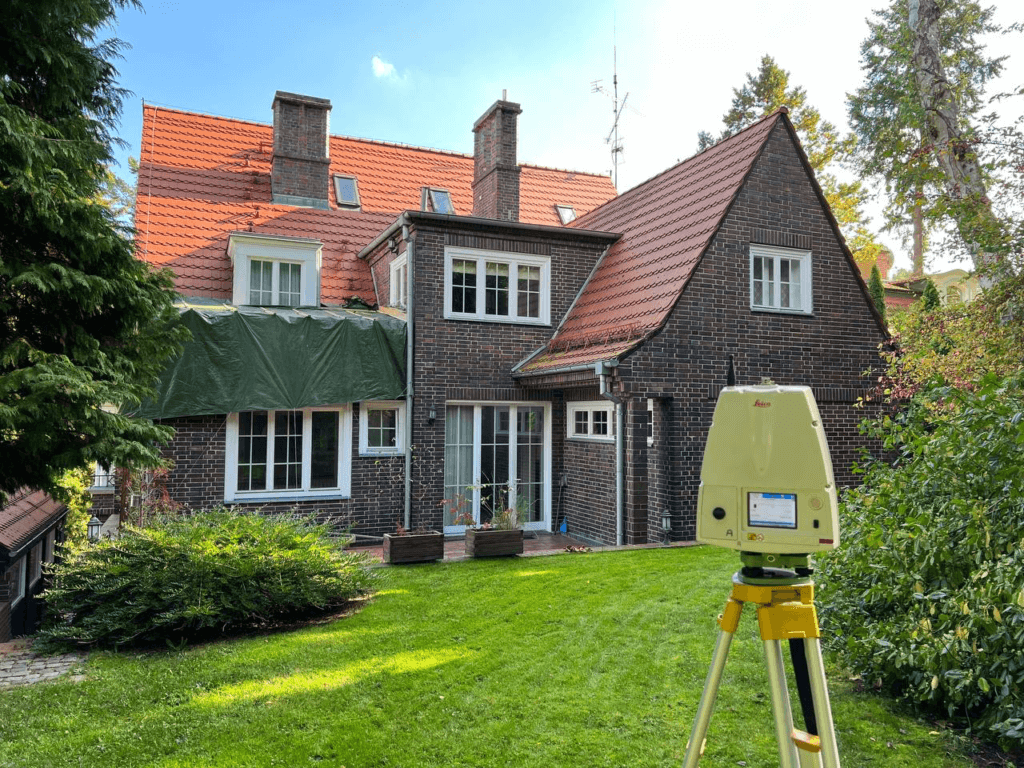
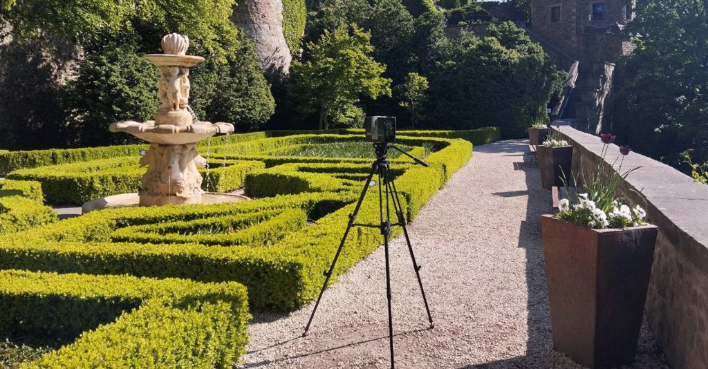
3D laser scanning for historic buildings improves documentation by capturing large volumes of spatial information quickly and with high geometric fidelity. Instead of collecting isolated dimensions, the scanning process records the visible form of the building as a dense spatial dataset that can later be measured, interpreted, and translated into usable documentation.
For heritage buildings, this offers several advantages:
- more complete capture of complex geometry,
- better recording of facade detail and surface variation,
- reduced dependence on fragmented manual measurements,
- stronger basis for plans, sections, and elevations,
- reliable documentation for restoration and conservation teams.
In practice, laser scanning for heritage documentation makes it easier to build documentation around what truly exists. That is especially useful when the building has been altered over time or when a high degree of documentation confidence is needed before intervention begins.
Point Cloud as the Basis for Accurate Heritage Records
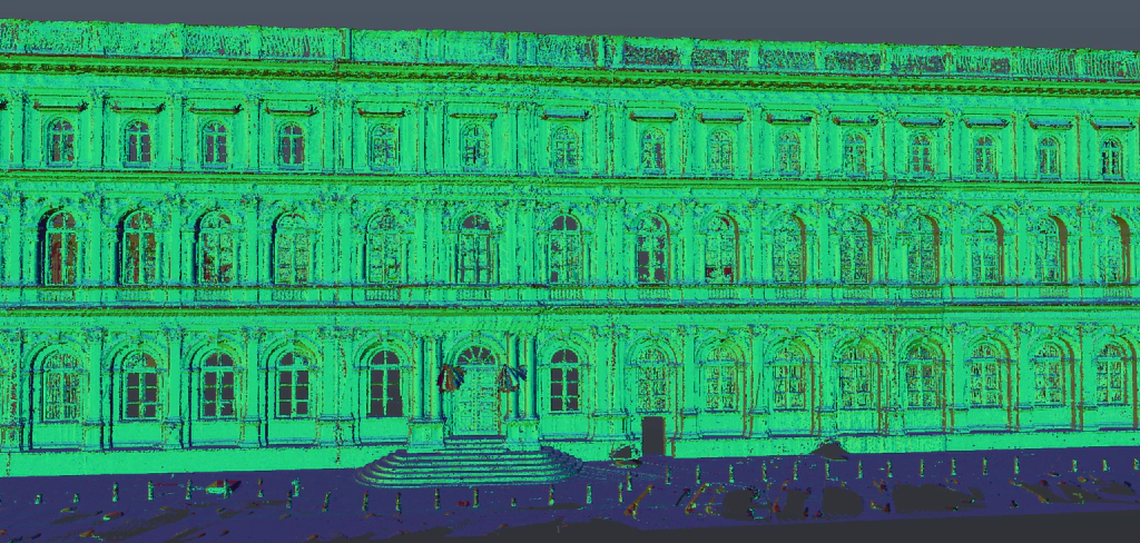
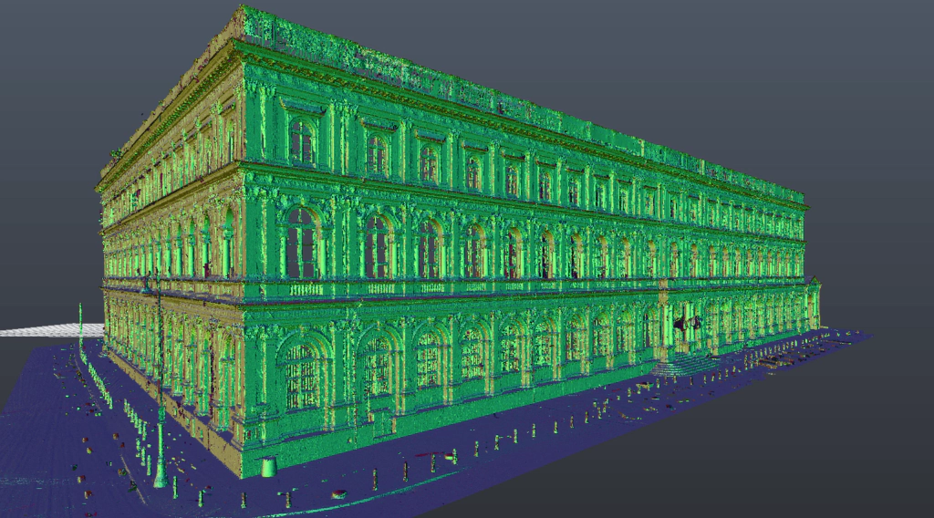
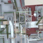
One of the most valuable outputs of laser scanning is the point cloud. A point cloud provides a measurable geometric reference of the building and often becomes the foundation of the documentation process.
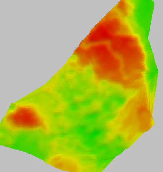
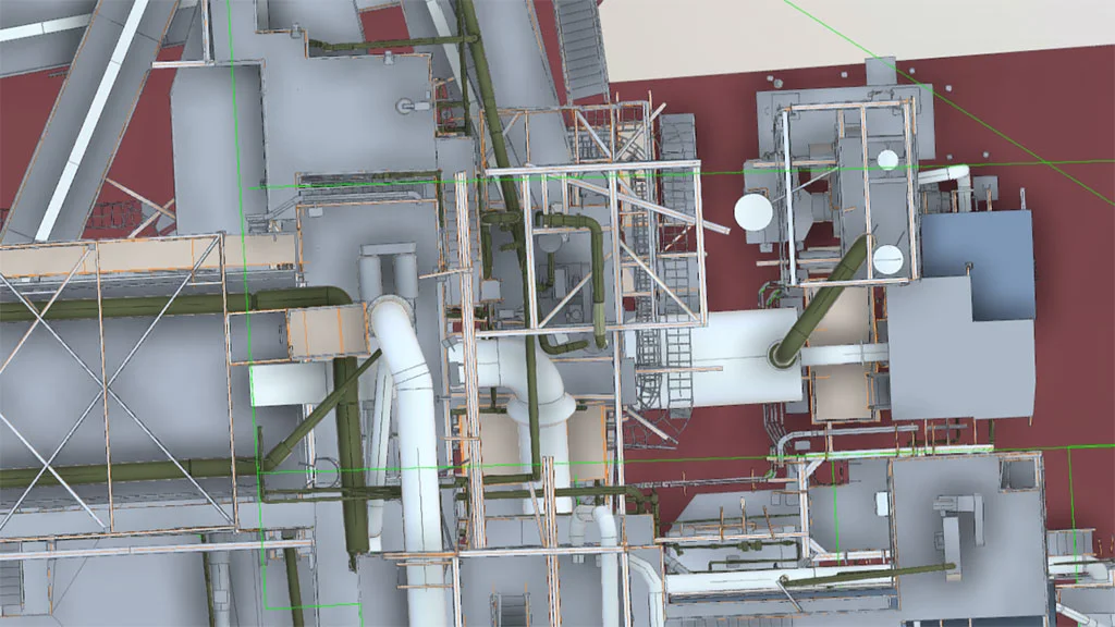
For point cloud for heritage buildings, the value lies in its ability to represent:
- actual building geometry,
- distortions and irregularities,
- complex roof and facade forms,
- openings, profiles, and ornamented surfaces,
- visible structural and architectural relationships.
A point cloud is not the final documentation by itself, but it becomes the source from which accurate heritage records can be created. In many cases, this is the most dependable basis for point cloud documentation of historic buildings, particularly when legacy drawings are incomplete or unreliable.
What Deliverables Can Be Created from Heritage Building Scans
A heritage documentation workflow based on laser scanning can produce a wide range of outputs depending on project goals. These outputs may support conservation, design, restoration, building analysis, or long-term digital archiving.
Typical deliverables include:
- measured floor plans,
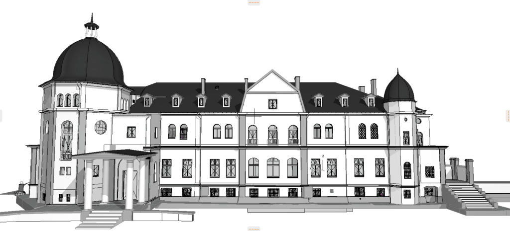
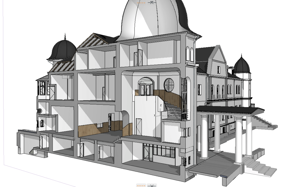
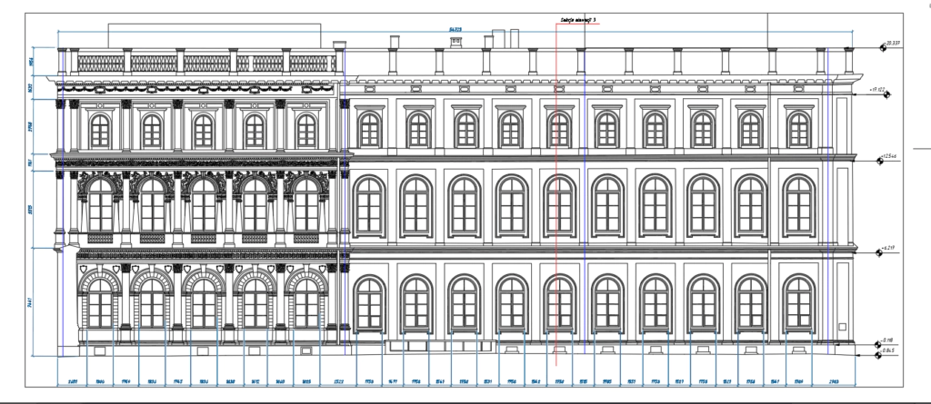
- sections and elevations,
- facade documentation,
- reflected ceiling plans where needed,
- orthographic views,
- as-built architectural records,
- point cloud datasets,
- digital model references for further development.
Where broader digital workflows are required, this can also connect with BIM modeling services for structured model development and coordination support.
How Architectural Documentation Supports Restoration and Conservation
Accurate documentation is essential before restoration or conservation work begins. Without a reliable record of actual conditions, it becomes difficult to assess what should be preserved, what has changed over time, and how new interventions may affect the building.
For this reason, scan-based documentation is highly relevant to conservation planning. It supports:
- understanding of the existing architectural condition,
- comparison between historical records and current geometry,
- careful planning of interventions,
- preservation of important facade and structural features,
- coordination between architects, engineers, and conservation professionals.
This is also where the topic overlaps with 3D Scanning for Cultural Heritage Conservation, since both workflows depend on measured reality as the basis for responsible heritage decisions.
The Role of HBIM in Heritage Documentation
When documentation workflows move beyond drawings and into structured digital models, the discussion naturally connects to HBIM. For many projects, architectural documentation is the first step that later supports historic-building BIM development.
A scan-based documentation process can feed into broader digital workflows such as What Is HBIM and How It Is Used for Historic Buildings, especially when the project requires not only drawings but also a model that can organize building information, support restoration planning, and preserve knowledge about the structure over time.
In that sense, documentation, point clouds, and model-based workflows are not separate tasks. They are often part of one continuous process.
Why Accurate Existing Conditions Matter Before Renovation
Before any renovation or adaptive reuse project begins, teams need confidence in the data they are using. In historic buildings, poor assumptions at the beginning of the project can cause redesign, coordination issues, scope change, and avoidable construction risk later.
Accurate digital documentation of historic buildings helps reduce that risk by making existing conditions visible, measurable, and shareable across disciplines. Instead of starting from uncertainty, the project begins with dependable geometric evidence.
This is particularly important in:
- renovation of listed or historic properties,
- heritage-sensitive design development,
- facade restoration,
- structural strengthening projects,
- modernization of historic public buildings,
- complex reuse schemes.
Why ScanM2
At ScanM2, we work with scan-based building documentation, point cloud workflows, digital modeling, and existing-condition deliverables for architecture and heritage-sensitive projects. We understand that architectural documentation of heritage buildings is not only about producing drawings. It is about creating a dependable record of the building that can support preservation, design, and technical decision-making.
Our approach combines measured data, structured documentation, and practical output formats that are useful for real projects. Whether the goal is facade documentation, restoration planning, digital archiving, or a broader model-based workflow, the focus remains the same: accurate information based on the real building.
FAQ
What is architectural documentation of heritage buildings?
It is the process of recording the geometry, condition, and architectural features of historic buildings in the form of drawings, measured records, point cloud data, and related documentation outputs.
Why is 3D laser scanning useful for heritage documentation?
It captures accurate spatial information from complex historic buildings and provides a strong basis for plans, sections, elevations, and existing-condition records.
Can point clouds be used for historic building documentation?
Yes. Point clouds are often one of the most reliable sources for documenting the real geometry of heritage buildings and creating accurate records.
What deliverables can be created from heritage scanning?
Typical outputs include floor plans, sections, elevations, facade records, orthographic views, as-built documentation, and point cloud datasets.
Is laser scanning better than traditional measurement for historic buildings?
In many cases, yes. It is especially useful when the building has irregular geometry, complex details, or needs highly accurate documentation before restoration.
Can scan-based documentation support BIM workflows?
Yes. Heritage documentation created from scans can support structured digital workflows and later connect with BIM or HBIM development.