

As-Built Drawings for Thermal power station
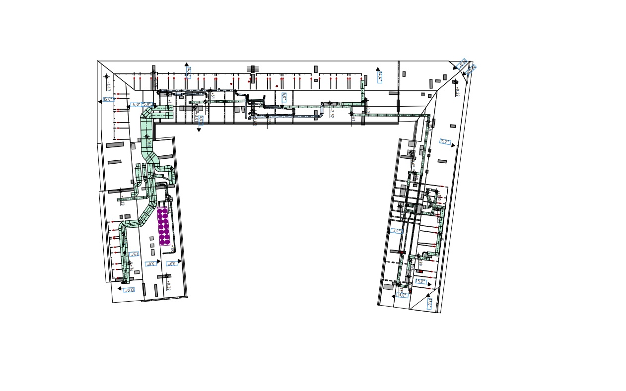
Technical drawings are essential for the operation, reconstruction, and modernization of thermal power stations. However, documentation created during original construction may no longer reflect the actual arrangement of equipment, pipelines, supporting structures, and technical spaces. Years of repairs, equipment replacement, and local modifications can create significant differences between historical plans and existing conditions.
ScanM2 provides As-Built Drawings Services for Thermal Power Stations, preparing measured plans, sections, elevations, and equipment layouts based on available survey data and verified technical information. Our documentation supports engineering design, facility reconstruction, equipment modernization, and the assessment of existing industrial infrastructure.
Contact Us Now for a Free Consultation!
When Original Power Station Drawings No Longer Match Reality
A thermal power station may remain operational for decades while its equipment and infrastructure undergo repeated changes. Steam lines are rerouted, pumps are replaced, maintenance platforms are modified, and technical openings are introduced into existing structures.
These modifications are not always reflected in the available documentation. As a result, engineers preparing a new project may encounter discrepancies between drawings and actual site conditions.
As-built documentation provides an updated geometric reference for the surveyed areas. It helps project teams understand what is physically present before developing new equipment arrangements or reconstruction solutions.
Drawing Packages for Different Areas of a Thermal Power Station
Power generation facilities contain buildings and technical systems with different documentation requirements. The drawings required for a boiler installation may differ considerably from those needed for a turbine hall or auxiliary pump station.
| Plant area | Typical as-built drawings | Engineering application |
|---|---|---|
| Boiler house | Floor plans, sections, equipment arrangements, structural elevations | Boiler modernization and technical system coordination |
| Turbine hall | Equipment layouts, foundation plans, building sections | Turbine-generator replacement and reconstruction |
| Piping galleries | Pipe routing plans, elevations, selected sections | Pipeline modification and spatial coordination |
| Pump stations | Equipment layouts, connection locations, structural plans | Pump replacement and auxiliary system upgrades |
| Technical buildings | Architectural plans, structural drawings, elevations | Building refurbishment and infrastructure modifications |
| Equipment foundations | Foundation layouts, measured sections, reference dimensions | Equipment installation planning and interface assessment |
The final documentation package is determined by the project’s objectives, available measurement data, and the level of detail required for engineering use.
Boiler House Plans and Sections
Boiler houses are among the most spatially complex areas of a thermal power station. Large equipment assemblies, steel platforms, ducts, pipelines, and service structures occupy multiple elevations within the same building.
Conventional floor plans alone may not provide enough information to understand this arrangement. Vertical sections and elevations are often necessary to document relationships between equipment, platforms, building structures, and technical systems.
Depending on the scope, drawings can show major equipment boundaries, accessible structural members, floor levels, openings, and relevant piping or duct routes.
Documenting Multi-Level Industrial Spaces
Industrial boiler buildings may contain numerous platforms and service levels that do not correspond to conventional building floors. As-built drawings must represent these elevations clearly enough for designers to understand equipment access and structural relationships.
Selected sections can help identify the vertical position of platforms, equipment supports, and technical installations relative to an agreed reference level.
Turbine Hall Documentation for Equipment Replacement
Replacing or modernizing turbine-generator equipment requires accurate information about the surrounding installation environment. Existing foundations, structural columns, floor openings, platforms, and adjacent machinery may impose important spatial constraints.
As-built drawings can document the arrangement of the turbine hall and provide measured reference dimensions for subsequent engineering work.
For equipment replacement projects, documentation may focus on foundation locations, equipment envelopes, accessible mounting interfaces, and surrounding structural geometry.
Where detailed reconstruction of individual mechanical components is required, Reverse Engineering Services for Thermal Power Stations can address component-level geometric reconstruction as a separate task.
Piping Layouts and Technical Network Drawings
Steam, feedwater, condensate, cooling-water, and auxiliary piping networks are essential elements of thermal power station infrastructure. Their routes may pass through several buildings and technical levels.
Measured drawings can represent the spatial arrangement of accessible pipelines, supports, and connection areas where sufficient source data is available.
Depending on the requirements, deliverables may include routing plans, elevations, selected sections, and equipment connection layouts.
Geometric piping drawings should not be confused with verified process and instrumentation diagrams. Flow direction, operating parameters, pipe specifications, and instrumentation information require appropriate engineering documentation and validation.
How We Establish the Geometry of Existing Facilities
The reliability of as-built drawings depends on the quality and completeness of the source measurements. Existing drawings may provide useful background information, but they should not automatically be treated as verified records of current site conditions.
For complex industrial environments, 3D laser scanning can capture accessible surfaces of buildings, structures, and equipment from multiple positions.
Our 3D Laser Scanning Services for Thermal Power Stations can provide the measurement basis for developing updated technical drawings.
Registered point clouds allow drafting specialists to examine the existing geometry and extract relevant dimensions, sections, and spatial relationships. Additional field measurements may be required for concealed, inaccessible, or critical features.
Measured Geometry and Engineering Interpretation
An as-built drawing should distinguish between geometry supported by actual measurements and information derived from other sources.
For example, a laser scan may accurately capture the visible external surface of a pipe or equipment housing. It does not automatically establish the internal diameter, wall thickness, material specification, or concealed connections.
Likewise, inaccessible surfaces behind insulation or equipment cannot be represented as directly measured without additional investigation.
Where project requirements call for combining measured geometry with existing technical drawings, the sources and limitations should be understood by the engineering team.
Choosing the Right Drawing Scale and Level of Detail
The appropriate documentation detail depends on the intended engineering task. A general building plan used for preliminary reconstruction planning may require less detail than a drawing prepared to evaluate an equipment installation interface.
Before drafting begins, the project team should establish which objects must be represented, which dimensions are critical, and how the drawings will be used.
Important decisions may include:
- Required plans, sections, elevations, and equipment layouts
- Drawing scales and coordinate references
- Technical systems to be included or excluded
- Required dimensions and elevation markers
- Representation of inaccessible or unverified elements
- CAD file organization and delivery requirements
As-Built Drawings for Phased Thermal Power Station Reconstruction
Modernization projects at operating thermal power stations are frequently divided into separate stages. Different generating units, technical systems, or buildings may be surveyed and reconstructed at different times.
As-built documentation can be prepared for individual project zones, allowing engineering teams to work with the relevant existing-condition information without requiring complete documentation of the entire facility.
For example, a project may initially require turbine hall plans and foundation layouts. A later stage may involve piping galleries or auxiliary equipment rooms.
When drawings are developed from surveys conducted on different dates, the documentation should identify the applicable survey scope and reference condition. This is particularly important where equipment arrangements have changed between measurement campaigns.
From Point Clouds to CAD Drawings
Registered point cloud data can serve as a geometric reference for preparing 2D technical documentation. Drafting specialists extract relevant plans, sections, and elevations from the measured dataset.
Before drafting, the scan data may require registration checks, filtering, organization, and conversion into suitable formats. Point Cloud Processing Services for Thermal Power Stations supports this preparation stage.
The drafting process then converts the required measured geometry into conventional CAD elements, dimensions, annotations, and drawing layouts.
The result is a technical drawing package rather than a direct export of every measured point. Relevant details must be selected and represented according to the agreed documentation requirements.
Our As-Built Documentation Workflow
We organize the documentation process around the specific plant areas and engineering decisions that the drawings must support.
- Documentation scope. Define the plant areas, required drawing types, dimensions, and intended engineering applications.
- Source review. Examine available drawings, survey records, and technical information.
- Measurement planning. Determine whether existing source data is sufficient or additional field measurements are necessary.
- Geometric interpretation. Review the measured data and identify the structures, equipment, and technical systems required in the drawings.
- CAD drafting. Prepare plans, sections, elevations, and layouts according to the agreed requirements.
- Documentation review. Check relevant geometry, dimensions, references, and drawing consistency.
- File delivery. Provide the agreed CAD and document formats for engineering use.
What the Client Receives
The final package is tailored to the surveyed areas and the requirements of the reconstruction or modernization project.
Depending on the scope, deliverables may include:
- Measured floor plans of industrial buildings
- Building sections and elevations
- Boiler and turbine equipment arrangement drawings
- Equipment foundation and support layouts
- Selected piping route plans and sections
- Technical opening and platform documentation
- Editable CAD drawings in agreed formats
- PDF drawing sets for review and distribution
Where required, measured documentation can also serve as source information for BIM Modeling Services for Thermal Power Stations, supporting coordinated three-dimensional representation of existing and proposed plant systems.
Why Updated Drawings Matter Before Equipment Modernization
Reconstruction decisions based on outdated documentation can lead to incorrect assumptions about available space, existing support locations, and equipment connections.
Updated as-built drawings provide a clearer basis for engineering coordination by documenting the relevant visible and measurable conditions of the facility.
They can help project participants identify spatial restrictions, compare proposed layouts with existing structures, and determine where additional detailed measurements or technical investigations are required.
As-built documentation does not replace engineering calculations, structural assessment, or equipment certification. Its primary role is to provide reliable geometric information within the defined measurement and drafting scope.
As-Built Documentation for Thermal Power Station Projects
Every thermal power station has a unique combination of original construction, later modifications, operational restrictions, and technical documentation. An effective as-built drawing package must reflect these conditions rather than follow a generic drawing checklist.
ScanM2 prepares measured technical drawings for complex industrial facilities, supporting reconstruction planning, equipment replacement, and engineering documentation. Contact our team to discuss the required plant areas, available drawings, and expected deliverables.

