

BIM LOD Explained: LOD 100, 200, 300, 350, 400 and 500 With Examples
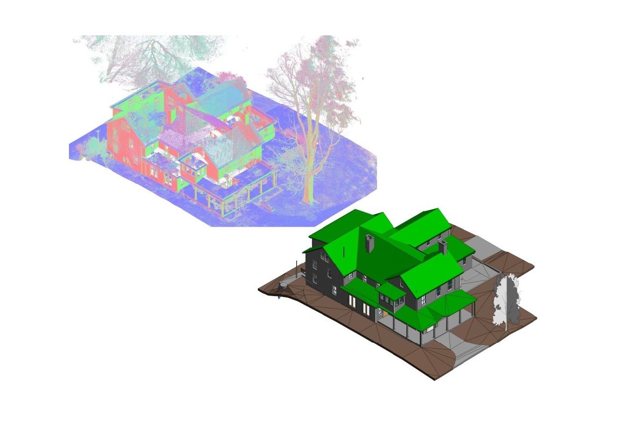
Level of Development (LOD) is a scale used in BIM to state how far a model element has been developed and how much the project team can rely on it. It runs from LOD 100 (a symbol or rough placeholder) to LOD 400 (detail sufficient for fabrication and installation), with LOD 500 reserved for elements that represent existing, field-verified conditions. LOD is assigned per element, not per model, and it is the most common way to write clear BIM scope into contracts and BIM execution plans.
This guide walks through every level using the same element, a supply air duct, so you can see exactly what changes from one LOD to the next. It also covers a question most LOD guides skip: what LOD you can realistically expect from a model built from a laser scan of an existing building.
Where the LOD Definitions Come From
The LOD scale was first published by the American Institute of Architects (AIA) in 2008. In the US, the practical reference today is the BIMForum Level of Development (LOD) Specification, which BIMForum started developing in 2011 and still updates. The 2025 version uses the LOD definitions from AIA Contract Document E201-2022, is organized by CSI UniFormat, and illustrates what each LOD means for individual building systems: walls, foundations, ductwork, piping, electrical and more.
Several points from the specification are worth knowing before you write LOD into a contract:
- There is no such thing as an “LOD 300 model.” A model at any stage contains elements at different levels. A 100% schematic design model will include elements at LOD 100, 200 and some at 300.
- LOD requirements are minimums and cumulative. A highly detailed element that is not located accurately can be no higher than LOD 200.
- The specification is a shared language, not a set of requirements. The project sets the targets, usually in a BIM execution plan (BEP).
Level of Development vs. Level of Detail vs. LOI
These three terms are often mixed up:
- Level of Detail is how much detail is drawn in an element: how it looks.
- Level of Development is how far the element’s geometry has been thought through: how much others can rely on it. This is what “LOD” means in BIMForum and US contracts. Some countries call the same concept “Level of Detail” and number it differently.
- Level of Information (LOI) describes the non-graphic data attached to an element: manufacturer, model number, airflow, fire rating, maintenance data. Under the 2022 AIA definitions, any amount of non-graphic information can be attached at any LOD. So LOD does not tell you what data an element carries. Specify that separately, in the BEP or an LOD/LOI matrix.
The 2025 specification also maps LOD 100–400 to the aspects of ISO 7817-1, which helps on projects that follow ISO 19650.
LOD 100–500 at a Glance
| LOD | What is modeled | Typical use | Example: supply air duct | Example: interior wall |
|---|---|---|---|---|
| 100 | Symbol, generic representation or space reservation. Information may come from other elements | Concept, feasibility, early cost per area | An “HVAC zone” or space reserved in a ceiling, no duct geometry | A room boundary or line showing a partition exists |
| 200 | Generic 3D placeholder with approximate size, shape, location and orientation | Schematic design, early layouts | Schematic main and riser routes with approximate size | Generic wall with approximate thickness and location |
| 300 | Element as designed; size, shape, location and orientation can be measured from the model | Design development, construction documents, quantities | Design-specified size and location of ducts, dampers, fittings and insulation; clearance allowances | Specific wall type, accurate thickness, height and location |
| 350 | LOD 300 plus measurable interfaces with adjacent elements | Construction-level coordination, clash detection | Actual sizes and connections, hangers and supports, floor and wall penetrations, access clearances | Wall with its connections to floor, ceiling and structure, and openings for MEP penetrations |
| 400 | Detail sufficient for fabrication, assembly and installation | Shop drawings, prefabrication | Fabrication-ready duct sections with supplementary components needed for installation | Wall panel modeled for prefabrication, with studs and fastening |
| 500 | Representation of an existing or as-constructed condition from observation, field verification or interpolation, with its accuracy stated | As-built records, renovation, operations | Existing duct modeled from a laser scan, with stated accuracy | Existing wall modeled from scan data, with stated accuracy |
LOD 100: Symbol or Placeholder
At LOD 100 an element does not need real geometry. It can be a symbol, a note attached to another element, or a volume reserving space. Anything derived from it, such as cost per square foot or HVAC tonnage, is approximate.
Duct example: the model shows an HVAC zone and a reserved volume above the corridor ceiling. Nobody can measure a duct yet, but the architect knows that space has to stay free.
LOD 200: Generic, Approximate Geometry
LOD 200 elements are 3D and recognizable for what they are: a pump, a beam, a light fixture. Quantity, size, shape, location and orientation are all approximate.
Duct example: the mechanical engineer lays out schematic mains and risers with approximate sizes. You can see that the main runs along the corridor and drops at the shaft. You cannot yet trust the exact elevation or the size of each branch.
LOD 300: Accurate Design Geometry
At LOD 300 the element is modeled as designed, and you can measure its size, shape, location and orientation directly from the model. BIMForum notes that designers rarely model beyond LOD 300, and that LOD 300 elements are not necessarily clash-free. They are modeled at accurate size so the team can estimate the space needed.
Duct example: ducts, dampers, fittings and insulation for risers, mains and branches are modeled at design-specified size and location. Space for hangers, supports and access clearances is included as an approximate allowance.
LOD 350: Interfaces and Coordination
BIMForum created LOD 350 to describe elements developed enough for detailed coordination between disciplines: clash avoidance, clash detection and layout. It was later adopted into the 2022 AIA documents. LOD 350 adds measurable interfaces with adjacent and dependent elements, and it usually requires trade (craft) knowledge.
Duct example: actual duct sizes and connections, actual hangers, supports, vibration and seismic controls, floor and wall penetrations, and code and access clearances are modeled. This is the level at which mechanical, electrical, plumbing and structural models can be checked against each other in a meaningful way. Coordination at this stage is the core of BIM clash detection.
LOD 400: Fabrication and Installation
LOD 400 elements are developed to the level of shop drawings. According to BIMForum, if the project specifications call for shop drawings of an item, the team might model that item at LOD 400, and most models contain few if any LOD 400 elements.
Duct example: duct is modeled in fabrication sections, with the supplementary components needed for fabrication and field installation. A sheet metal contractor can use it to fabricate and plan the installation.
LOD 350 vs. LOD 400: Which One Do You Need?
Both are “construction” levels, so they are easy to confuse. The difference is the purpose:
- LOD 350 answers “will it fit, and what does it connect to?” It is the right target for multi-trade coordination, sleeves and penetrations, and installation sequencing.
- LOD 400 answers “can we build it from the model?” It belongs to the trade that fabricates the item, usually in prefabrication or shop drawing scopes.
Asking for LOD 400 across a whole model means paying for fabrication detail on items no one will fabricate from it, such as standard off-the-shelf components. A more practical scope is LOD 350 for coordination and LOD 400 only for systems that will be prefabricated. Our earlier article on when more BIM detail stops adding value looks at this trade-off in more detail.
LOD 500: As-Built, Existing Conditions and Facility Management
LOD 500 is the most misunderstood level. Many guides present it as “one step above LOD 400.” BIMForum states plainly that LOD 500 does not indicate a higher level than LOD 400. It means the element’s geometry comes from observing an existing item, not from designing a future one. The AIA definition requires that the element’s accuracy be noted or attached, and BIMForum recommends the USIBD Level of Accuracy (LOA) Specification for stating it.
In practice this means:
- An as-built model is only as useful as its stated accuracy and the elements it actually includes.
- LOD 500 says nothing about information. For facility management, owners usually care more about LOI (equipment tags, model numbers, service data, room data) linked to correctly located elements. A good FM model is often simpler in geometry than a construction model but richer in data. See how we approach as-built documentation for facility management.
Duct example: after construction, or in a building you are about to renovate, the duct is modeled from laser scan data. Its location and size come from measurement, and the model states the accuracy it was produced to.
LOD for Scan to BIM and Existing Conditions
When a model is built from a point cloud, LOD works differently, because nothing is being designed. This is where scope disagreements usually start.
What LOD is realistic from a laser scan
A laser scanner records only what it can see. For visible elements, such as walls, columns, slabs, exposed structure, exposed ducts and pipes, and equipment, a Scan to BIM model can reach geometry that is equivalent to LOD 300, and LOD 350 where connections, supports and penetrations are visible in the scan. Under the AIA/BIMForum definitions, such elements are formally LOD 500 because they represent observed conditions, and their accuracy should be stated.
Hidden elements are different. Ducts above a closed ceiling, pipes inside walls and rebar in concrete are not in the point cloud. They can be modeled from existing drawings or assumptions, but they should be marked as unverified. They are not field-verified, whatever level of detail they are drawn at.
LOD 400 is rarely a meaningful target for existing conditions. It describes fabrication-ready design. An existing duct is not going to be fabricated again from the model. If a contractor needs precise tie-in points for new prefabricated work, define those points and their tolerance explicitly instead of asking for “LOD 400” for the whole existing building.
Why ±2–3 mm scan accuracy does not mean LOD 400
Terrestrial laser scanning (for example, with FARO scanners) typically delivers point clouds accurate to about ±2–3 mm. That is the accuracy of the point cloud, not of the model. Three separate things come into play:
- Scan accuracy: how closely the registered point cloud matches the real building (typical ±2–3 mm for terrestrial laser scanning, depending on the scanner, range and registration).
- Modeling tolerance: how far the modeled element may deviate from the point cloud. Real walls are not perfectly flat or plumb, and real ducts sag. A Revit wall is a straight, uniform object, so the modeler fits idealized geometry to an irregular surface. The allowed deviation is a scope decision, not a property of the scanner.
- LOD: which elements and which parts of them are modeled at all.
A model can be built from a very accurate scan and still be LOD 200 for some elements, if that is all the project needs. And an element modeled at LOD 350 detail is only as reliable as the modeling tolerance that was agreed. That is why BIMForum asks for accuracy to be stated separately for LOD 500 elements, instead of folding it into the LOD number.
Agree LOD per element and discipline in a BEP
For Scan to BIM, the most reliable scope is an LOD matrix in the BIM execution plan, which lists each element category and states:
- the target LOD (for example, architectural walls and openings at 300, exposed MEP mains at 350, small devices as families or not modeled);
- size thresholds: BIMForum gives the example of conduit under 1/2″ not being modeled. Decide what pipe, duct and conduit sizes are excluded;
- the modeling tolerance against the point cloud, by element type;
- how hidden or unverified elements are handled and marked;
- the LOI: which parameters each element must carry;
- the delivery format: native Revit (.rvt), .ifc, or both.
This prevents the most common Scan to BIM dispute: the client expected every valve and conduit, and the modeler priced walls, floors and main systems. For a practical list of what is worth modeling from a scan and what is not, see Revit modeling from point cloud: what should be modeled and what shouldn’t.
How to Choose the Right LOD for Your Project
Use this checklist before you write an LOD requirement into a contract or RFP:
- Start from the use, not the number: design, coordination, fabrication, renovation and operations need different content.
- Set LOD per element category and milestone, never one number for the whole model.
- Use LOD 350 for coordination; keep LOD 400 for items fabricated from the model.
- Specify LOI separately, especially for handover and facility management.
- For existing buildings, add accuracy and modeling tolerance, and agree how hidden elements are treated.
- Name the reference, for example “BIMForum LOD Specification, 2025,” and agree formats (.rvt, .ifc) up front.
FAQ
What is the difference between LOD 300 and LOD 350?
Is LOD 500 higher than LOD 400?
What LOD is typical for Scan to BIM?
Does a ±2–3 mm laser scan give me an LOD 400 model?
What is the difference between LOD and LOI?
Need a Model at the Right LOD?
ScanM2 scans existing buildings across the US. We travel to any state, or work from point clouds you already have, and deliver Revit models and .ifc files with LOD, tolerance and LOI agreed per element before modeling starts. Explore our Scan to BIM services for existing conditions, or our Revit BIM modeling services for design and coordination models.

ScanM2 Launches ScanTrack: Manage Tasks Directly in a 3D Virtual Tour
18.10.2026
How integrating as-built documentation using advanced 3D scanning and laser scanning technology can revolutionize your real estate marketing strategy. Learn the benefits for agents and ...
Which 3D Laser Scanner Should Architects Choose, and When Is Outsourcing Better?
17.10.2026
How integrating as-built documentation using advanced 3D scanning and laser scanning technology can revolutionize your real estate marketing strategy. Learn the benefits for agents and ...

INTERGEO: How Laser Scanning Is Becoming a Foundation for Management and Decision-Making
24.09.2026
ScanM2 once again took part in INTERGEO, which was held in Munich this year. For us, the event is an opportunity to meet with partners, ...

How 3D Laser Scanning Measures Floor Flatness and Levelness
22.09.2026
Floor flatness and levelness can directly affect equipment installation, racking systems, automated material handling, production lines, flooring systems, and other construction activities that depend on ...

