

How 3D Laser Scanning Measures Floor Flatness and Levelness
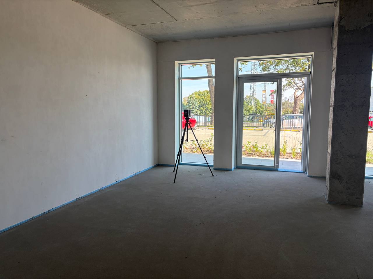

Floor flatness and levelness can directly affect equipment installation, racking systems, automated material handling, production lines, flooring systems, and other construction activities that depend on accurate floor geometry.
Traditional floor surveys typically rely on measurements taken at selected locations. While these methods can be appropriate for many applications, they provide information only at the points or lines that were actually measured.
3D laser scanning provides a different approach. By capturing dense spatial data across accessible floor surfaces, laser scanning creates a point cloud that can be used to analyze elevations, slopes, local irregularities, and deviations across large areas.
For existing buildings, industrial facilities, warehouses, and construction projects, this makes laser scanning particularly useful when a detailed understanding of actual floor geometry is required.
What Are Floor Flatness and Floor Levelness?
Although the terms are sometimes used together, floor flatness and floor levelness describe different characteristics of a floor.
Floor flatness refers to local variations in the surface. A floor may contain small bumps, depressions, waves, or other short-distance irregularities even if its overall elevation is relatively consistent.
Floor levelness describes how the elevation of the floor changes across a larger distance. A surface can be relatively flat locally while still having an overall slope or elevation difference from one side of the space to another.
This distinction matters because different projects may require different types of analysis.
For example, equipment installation may depend on local surface conditions, while a renovation project may require a broader understanding of floor elevations across an entire building.
Why Is Floor Geometry Important?
Small variations in floor geometry may have little impact in some buildings but become critical in others.
Accurate floor information can be important for:
- industrial equipment installation;
- machinery foundations;
- warehouse racking;
- automated storage and retrieval systems;
- conveyors and production lines;
- raised floors;
- interior renovation;
- flooring installation;
- drainage planning;
- structural assessment;
- coordination with doors, ramps, and adjacent spaces.
In existing buildings, actual floor conditions may also differ significantly from the original drawings.
Settlement, previous renovations, construction tolerances, wear, repairs, and structural movement can all influence the geometry measured today.
A detailed floor flatness survey or floor levelness survey can therefore provide useful information before new equipment, finishes, or building systems are designed around existing conditions.
How Does 3D Laser Scanning Measure a Floor?

A terrestrial laser scanner records spatial coordinates from surfaces visible from each scanner position.
During a floor survey, scanners are positioned throughout the required area so that the accessible floor surface is captured from multiple locations.
A typical laser scanning workflow can be represented as:
Site Survey → 3D Laser Scanning → Scan Registration → Point Cloud → Floor Surface Analysis → Deliverables
Individual scans are registered into a common coordinate system. The resulting point cloud contains large numbers of measured points representing the geometry of the floor and surrounding building elements.
Instead of recording only selected spot elevations, the dataset provides much denser spatial coverage of the accessible surface.
Specialists can then analyze the point cloud to determine how the floor elevation changes across the surveyed area.
What Can Be Measured from the Point Cloud?
Once the scans have been registered and checked, the point cloud can be used for several types of floor analysis.
Depending on the project requirements, measurements may include:
- floor elevations;
- elevation differences;
- local high and low areas;
- slopes;
- surface irregularities;
- transitions between rooms or zones;
- relative elevations between floors;
- deviations from a specified reference plane;
- relationships between the floor and surrounding structural elements.
A reference plane or project datum can be established and the measured surface compared against it.
This makes it possible to identify where the floor is higher or lower than the selected reference and to visualize how those deviations are distributed across the surveyed area.
Floor Elevation Mapping
One of the most useful outputs from laser scanning is a floor elevation map.
Instead of reviewing hundreds or thousands of individual elevation values, the measured surface can be represented visually.
A typical workflow may look like:
Point Cloud → Reference Plane → Elevation Calculation → Deviation Map
The resulting floor elevation mapping can show how elevation changes across the space and help identify areas requiring closer investigation.
Depending on project requirements, results may be presented as:
- elevation points;
- contour lines;
- color-coded deviation maps;
- sections and profiles;
- CAD drawings;
- numerical reports;
- point cloud datasets.
This is particularly useful for large floors where isolated spot measurements may not clearly show the overall pattern of variation.
Detecting High and Low Areas
Laser scanning can help locate localized high and low areas across a floor surface.
After the point cloud has been aligned to the required coordinate system, floor points can be compared with a reference elevation or plane.
Areas above the reference can be identified as higher zones, while areas below it can be identified as lower zones.
This type of floor deviation measurement can support planning for:
- leveling compounds;
- grinding;
- equipment installation;
- machinery alignment;
- raised floor systems;
- flooring replacement;
- renovation work.
Because the source data covers a large portion of the visible surface, the analysis can also reveal patterns that may be difficult to identify from a limited number of manually measured locations.
3D Laser Scanning vs Traditional Floor Measurement
Traditional measuring tools remain appropriate for many floor surveys. The choice of method should depend on the required accuracy, area, density of measurements, and intended use of the results.
For projects requiring extensive spatial documentation, however, laser scanning provides several practical differences.
| Traditional Floor Measurement | 3D Laser Scanning |
|---|---|
| Measurements are collected at selected locations | Dense measurements cover accessible floor surfaces |
| Additional measurements may require another site visit | Additional measurements can often be taken from the captured dataset |
| Results commonly consist of individual elevations or profiles | Results can be analyzed as a continuous spatial dataset |
| Large areas may require extensive field measurement | Large areas can be documented systematically |
| Limited surrounding geometry is recorded | Floors and surrounding building elements can be captured together |
The purpose is not necessarily to replace conventional surveying methods.
In many projects, 3D scanning and traditional measuring tools can complement each other, depending on the required deliverables and applicable measurement standards.
Concrete Floor Flatness Measurement
Concrete floors are one of the most common applications for detailed surface analysis.
Warehouses, factories, logistics facilities, parking structures, and commercial buildings may contain large concrete slabs where elevation variations affect later construction or operational requirements.
A concrete floor flatness measurement based on laser scanning can provide dense information about the visible slab surface.
This can help identify:
- localized surface irregularities;
- elevation changes;
- transitions between pours;
- high and low areas;
- slopes;
- differences between adjacent zones.
For existing facilities, the same approach can be used to document floors before renovation or installation of new equipment.
It is important, however, to distinguish general laser-scanning-based surface analysis from compliance testing performed under a specific standard. If a project requires certification or verification according to a particular floor-flatness standard, the measurement methodology and acceptance criteria should be defined accordingly.
Preparing the Point Cloud for Floor Analysis
Raw laser scanning data generally requires processing before detailed measurements are performed.
Multiple scans first need to be registered into a consistent coordinate system. The dataset is then reviewed to confirm sufficient coverage and identify information that is not relevant to the analysis.
Depending on site conditions, raw data may contain points representing:
- people;
- temporary materials;
- equipment;
- pallets;
- cables;
- construction debris;
- reflections;
- measurement noise.
Appropriate point cloud cleaning helps prepare the dataset for subsequent analysis.
For floor measurement, it is particularly important to distinguish the actual floor surface from objects resting on it. A scanner cannot measure a floor surface that is physically concealed by equipment, stored materials, or other obstacles.
How Accurate Is Laser Scanning for Floor Measurement?
The accuracy achievable in a floor survey depends on more than the specification of the scanner itself.
Important factors include:
- scanner model;
- distance from the scanner to the surface;
- scanning geometry;
- number and location of scanner positions;
- registration quality;
- site conditions;
- surface characteristics;
- required coordinate control;
- processing methodology.
For this reason, the required accuracy should be defined before the survey is planned.
A survey intended to provide a general elevation map may have different requirements from a survey intended to support precision equipment installation or detailed construction verification.
The measurement method should always be matched to the technical purpose of the project.
Floor Flatness Testing and Industry Standards
The terms floor flatness testing and floor levelness testing can also refer to formal measurement procedures defined by specific standards or project specifications.
For example, some concrete floor projects use numerical flatness and levelness criteria or other defined tolerances.
A dense laser scan can provide extensive geometric information about a floor, but this does not automatically mean that every laser scanning survey constitutes a certified test under a particular standard.
Before the survey, the project team should determine:
- which standard or specification applies;
- which measurements are required;
- how results must be calculated;
- what tolerances apply;
- whether a specific testing procedure is mandatory;
- what documentation must be delivered.
This distinction is especially important when floor measurements are being used for contractual acceptance, compliance, or formal quality-control purposes.
Floor Flatness Surveys for Existing Buildings

Existing buildings often present a different challenge from newly constructed concrete floors.
The objective may not be to verify a newly poured slab against construction tolerances. Instead, the goal may be to understand the actual geometry of a floor before a new project begins.
Examples include:
- installation of production equipment;
- warehouse modernization;
- relocation of machinery;
- installation of automated systems;
- interior reconstruction;
- installation of new flooring;
- coordination of ramps and access routes;
- assessment of existing drainage slopes.
In these situations, 3D laser scanning can document both the floor and its relationship with surrounding walls, columns, openings, equipment, and structural elements.
This broader spatial context can be particularly useful during design and coordination.
Using Floor Scan Data in CAD
After processing, floor survey data can be converted into documentation that is easier for engineers, architects, and contractors to use.
Depending on the project, a point cloud to CAD workflow can produce:
- floor plans;
- elevation plans;
- contour drawings;
- sections;
- profiles;
- reference grids;
- deviation drawings.
CAD documentation can simplify communication of measured conditions, especially when the complete point cloud contains more information than is necessary for the specific task.
For example, a contractor preparing a floor leveling scope may require a drawing showing high and low zones rather than the entire three-dimensional scan dataset.
Using Floor Scan Data in BIM
Floor geometry can also be incorporated into BIM workflows.
The point cloud can provide reference information for modeling existing floor elevations and coordinating new design elements with measured conditions.
This may be useful when planning:
- new equipment;
- partitions;
- ramps;
- raised floors;
- MEP systems;
- structural modifications;
- renovation work.
However, not every local irregularity should automatically be modeled as BIM geometry.
The required level of representation should depend on the purpose of the model. In many cases, detailed floor analysis can remain as point cloud or deviation data while the BIM model represents only the geometry necessary for design and coordination.
When Should a Floor Be Scanned?
The best time to perform a floor survey depends on what the data will be used for.
Laser scanning may be useful:
- before equipment installation;
- before warehouse automation projects;
- before renovation;
- before flooring replacement;
- after concrete construction;
- before installation of sensitive machinery;
- before preparation of leveling work;
- during existing-condition surveys;
- before major layout changes.
Whenever possible, the floor should be clear of unnecessary materials and equipment.
Better visibility allows the scanner to capture more of the actual surface and reduces areas where the floor is hidden by temporary objects.
Benefits of 3D Laser Scanning for Floor Flatness and Levelness
For suitable projects, laser scanning offers several practical advantages.
Dense Surface Data
Large numbers of measured points provide detailed information about the visible floor surface rather than only selected locations.
Floor Elevation Mapping
Measured elevations can be converted into maps that make high, low, and sloping areas easier to identify.
Large-Area Documentation
Warehouses, industrial facilities, and other large spaces can be documented systematically.
Reusable Measurement Data
Additional measurements and profiles can often be extracted from the point cloud after fieldwork is complete.
Building Context
The same survey can capture floors together with walls, columns, equipment, openings, and other surrounding elements.
Multiple Deliverables
The captured data can support point clouds, CAD drawings, elevation maps, profiles, BIM models, and other project-specific outputs.
Floor Surveys and 3D Laser Scanning at ScanM2
ScanM2 provides 3D laser scanning and point cloud processing for existing buildings, industrial facilities, warehouses, construction projects, and other complex environments.
Depending on project requirements, floor survey data can be processed to provide information about elevations, slopes, surface deviations, and relationships with surrounding building elements.
Deliverables can include registered point clouds, floor elevation data, CAD documentation, sections, profiles, deviation maps, and BIM models.
The required scanning and processing methodology is determined by the size of the area, site conditions, required accuracy, and intended use of the measurements.
Conclusion
Floor flatness and levelness can influence everything from equipment installation and warehouse automation to renovation and flooring work.
3D laser scanning provides a way to capture dense spatial information across accessible floor surfaces and analyze how elevations vary throughout the surveyed area.
The resulting point cloud can be used to identify high and low areas, evaluate slopes and elevation differences, create floor elevation maps, and prepare CAD or BIM documentation.
For large or geometrically complex spaces, the main advantage is not simply collecting more measurements. It is creating a reusable digital record of the floor and its surrounding environment that can support design, coordination, construction, and future analysis.
FAQ
Can 3D laser scanning measure floor flatness?
Can laser scanning measure floor levelness?
Can a floor elevation map be created from a point cloud?
Can laser scanning identify high and low areas of a concrete floor?
Is laser scanning suitable for large warehouse floors?
Does laser scanning replace traditional floor flatness testing?
What deliverables can be produced from a floor laser scan?

How 3D Laser Scanning Supports Construction Claims and Dispute Resolution
24.08.2026
Construction claims and disputes often arise when project participants disagree about what was actually built, when specific work was completed, whether installed elements match the ...

Point Cloud Cleaning Explained: How Scan Data Is Prepared for CAD and BIM
19.08.2026
3D laser scanning can capture millions or even billions of measurement points across an existing building, industrial facility, or construction site. However, the raw dataset ...

What Makes a Point Cloud Ready for BIM Modeling
08.06.2026
Many project teams assume that once a building has been scanned, the data is immediately ready for BIM modeling. In reality, the quality of the ...

What Architects Should Check Before Ordering a Scan-to-BIM Model
25.05.2026
Why Good Scan-to-BIM Projects Start Before Scanning Many architects approach Scan-to-BIM workflows expecting that laser scanning automatically produces a fully coordinated BIM model ready for ...

