

LOD 400 BIM Modeling Services
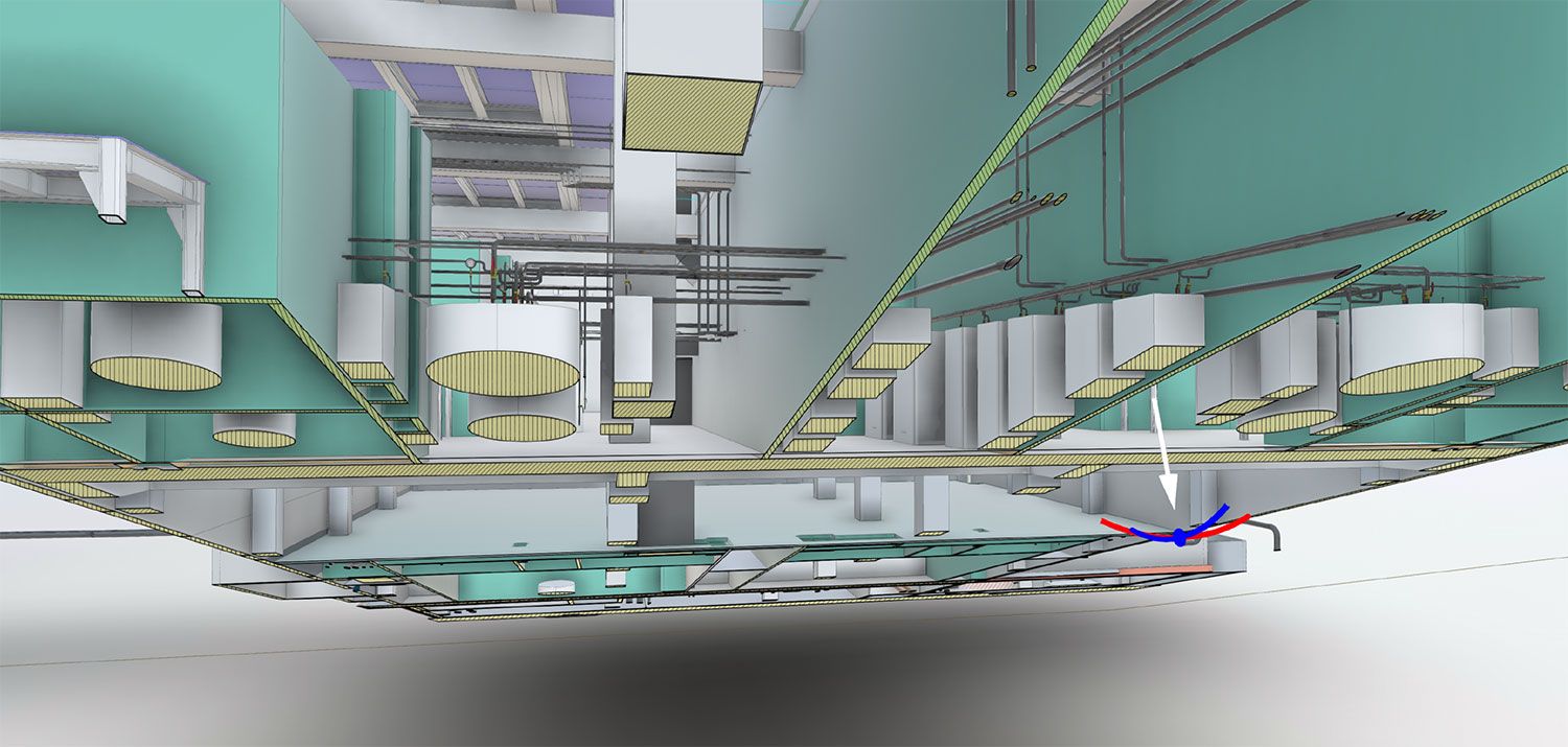
A LOD 400 model is the point where BIM stops being a design picture and becomes something a shop can build from. Duct runs are split into the sections that will be fabricated, pipes carry real fittings and valves, hangers sit where they will be anchored, and every element has the size, type and position of the product that will actually be installed. ScanM2 builds LOD 400 models in Autodesk Revit for MEP and fire protection contractors, fabricators, fit-out teams and general contractors – and, because 3D laser scanning is our core work, we can build them on top of the real existing building rather than on drawings that may be out of date.
Contact Us Now for a Free Consultation!
One thing we say upfront: LOD 400 cannot be produced from design drawings alone. It needs product data and decisions from the manufacturer, the installing contractor or both. We tell you exactly what is missing before modeling starts, so the model you get is genuinely fabrication-level and not LOD 300 with a different label.
What Is LOD 400?
LOD (level of development) describes how complete and reliable each element of a BIM model is. At LOD 300 an element has its design size, shape and location – a duct of the right size on the right route. At LOD 400 the same element is modeled as the specific product or assembly that will be built: real dimensions from the manufacturer, connections, joints, supports and the detail needed for fabrication and installation. For the full scale from LOD 100 to 500 and examples of each level, see our article BIM LOD Levels Explained.
| Element | LOD 300 | LOD 400 |
|---|---|---|
| Ductwork | Design size and route, generic fittings | Fabrication sections, real fittings, joints, access doors, hangers |
| Piping | Diameter, route, generic valves | Pipe material and joint type, specific valves and fittings, slopes, supports, insulation |
| Sprinkler systems | Mains, branches and heads at design locations | Specific heads and fittings, hangers and bracing as agreed, pipe lengths for prefabrication |
| Equipment | Generic box at the right size and location | Manufacturer model with connection points, service clearances, mounting |
| Cable trays and conduit | Main routes and sizes | Tray type, fittings, supports, drops to equipment |
| Structure | Members with design sizes | Connections, embeds and openings as needed for fabrication |
| Fit-out (walls, ceilings, millwork) | Wall types and ceiling heights | Framing layout, ceiling grid, panel and millwork layout from the selected system |
LOD 400 Needs Data From the Manufacturer and the Contractor
This is the part most LOD 400 projects underestimate. A BIM modeler can make a model detailed, but cannot invent the information that makes it buildable. To reach LOD 400, we need:
- Approved products and submittals – the actual equipment, valves, heads, fittings and materials, with their dimensions and connection data.
- Fabrication and installation standards – section lengths, joint and connection types, insulation thickness, the contractor’s preferred fitting types.
- Support and hanger decisions – hanger types, spacing rules and attachment method, as decided by the installing contractor and its engineer.
- Coordination rules – clearances, access zones, elevations reserved for each trade.
If some of this is not available yet, we model those elements to LOD 300 or 350 and mark them clearly in the model and in the issues list. We do not present an element as LOD 400 when the data behind it is a guess. We also do not perform structural or hydraulic calculations or stamp drawings – sizing, hanger loads and code compliance stay with your engineer of record; we model what has been decided.
LOD 400 on Existing Buildings: Start From the Real Conditions
On a renovation, retrofit or tenant fit-out, prefabrication fails most often not because the model is wrong, but because the building is different from the drawings. A beam sits lower than shown, a slab is out of level, an old duct was never removed. A spool that fits the model perfectly then does not fit the ceiling.
We solve this at the source. We scan the area with FARO laser scanners (typical accuracy ±2–3 mm), build an existing-conditions model from the point cloud, and model the new LOD 400 systems against it. The point cloud stays linked in Revit, so every new run can be checked against what is really there. See our Scan to BIM services and 3D laser scanning services. We travel to sites in any US state, or we work with point clouds your team or your scanning provider already has.
Disciplines We Model to LOD 400
- HVAC – ductwork, air terminals, dampers, equipment and supports. See also MEP BIM modeling.
- Plumbing and process piping – domestic water, sanitary, storm and process lines with real fittings, valves and slopes.
- Fire protection – sprinkler mains, branches, heads and fittings modeled for prefabrication. See our fire protection sprinkler BIM modeling.
- Electrical – cable trays, conduit racks, panels and equipment with connection points.
- Structure – steel and concrete elements, openings and embeds as needed for MEP and fit-out coordination. See Revit structural modeling.
- Architecture and fit-out – partitions, ceilings, millwork and interior systems based on the selected products. See Revit architecture modeling.
Industrial and oil & gas objects – piping, skids and equipment in existing plants – can also be modeled from point clouds at the level of detail your project needs.
Families Built for the Actual Products
LOD 400 lives and dies by its families. Generic Revit content rarely matches the equipment, valves or fittings that will be installed. When manufacturer families are missing or unusable, we build them from cut sheets and submittal data: correct geometry, connectors, clearances and parameters for schedules. See our Revit family creation services.
Coordination and Clash Detection
A LOD 400 model has value only if it is coordinated. We run clash tests in Navisworks and Revit between trades, between new systems and structure, and between the new model and the point cloud of the existing building. Clashes go into a report with viewpoints and are resolved in the model with your team. More on this in our BIM clash detection services.
Our LOD 400 Modeling Process
- Scope and data review. We agree the areas, disciplines, LOD per element type, Revit version and standards, and review submittals, design models and drawings. You get a list of what is missing for LOD 400.
- Existing conditions. We laser scan the site or take your point cloud and model the existing structure and services that matter for the new work.
- Families and content. We prepare or check families for the specified products.
- Modeling. New systems are modeled with real products, connections and supports, following the contractor’s fabrication and installation rules.
- Coordination. Clash tests, review meetings with your team and model updates until the agreed areas are coordinated.
- Quality check. A second specialist checks parameters, connections, levels and consistency against the source data.
- Sheets and export. We set up views and sheets from the model and export the formats you need.
What You Receive
| Deliverable | Details |
|---|---|
| Revit model (RVT) | LOD 400 elements in the agreed areas and disciplines, in your Revit version and template |
| Existing-conditions model | Structure and services built from the point cloud, linked to the new model |
| Families | Product families with connectors and parameters, delivered with the model |
| Views and sheets from the model | Plans, sections, 3D views and section or spool views set up on sheets for your team to review and issue |
| Clash reports | Clash tests with viewpoints and status, plus Navisworks files (NWC/NWD) |
| .ifc and other formats | .ifc export for other BIM software, DWG and PDF on request |
| Schedules | Equipment, fittings, valves and other element schedules from model data |
| Issues and assumptions list | Missing data, elements kept at LOD 300/350 and decisions made during modeling |
The sheets we produce are views from the coordinated model. Any shop drawings required for permits or approvals are reviewed and issued by your contractor or engineer of record.
When LOD 400 Is Not What You Need
LOD 400 takes more information and more modeling than LOD 300, and not every project benefits. For design development, permit sets, space planning or facility management, LOD 300 is usually the right level. LOD 400 makes sense where something will be fabricated or installed directly from the model: prefabricated MEP racks and spools, sprinkler prefabrication, tight ceiling spaces, plant rooms and fit-outs where every inch matters. We can also mix levels – LOD 400 for plant rooms and congested corridors, LOD 300 for the rest of the floor.
For a field-verified model for operations, see LOD 500 BIM modeling.
Who This Service Is For
- MEP and fire protection contractors preparing prefabrication and installation.
- Fabricators who need a coordinated model based on their own products.
- General contractors coordinating trades on renovations and fit-outs in existing buildings.
- Owners and facility teams planning plant room upgrades with minimal downtime.
FAQ
What is the difference between LOD 300 and LOD 400?
Can you create a LOD 400 model from design drawings only?
Can you build a LOD 400 model for an existing building?
Which disciplines do you model to LOD 400?
Do you produce shop drawings and spool drawings?
Do you create Revit families for specific products?
Is clash detection included?
What file formats do you deliver?
Send Us Your Project
Send us your design models or drawings, the list of approved products or submittals you already have, and a description of the area – or ask us to scan it. We review the information, tell you which elements can reach LOD 400 and what data is still needed, and send a quote based on the scope.

