

Fire Protection & Sprinkler BIM Modeling Services
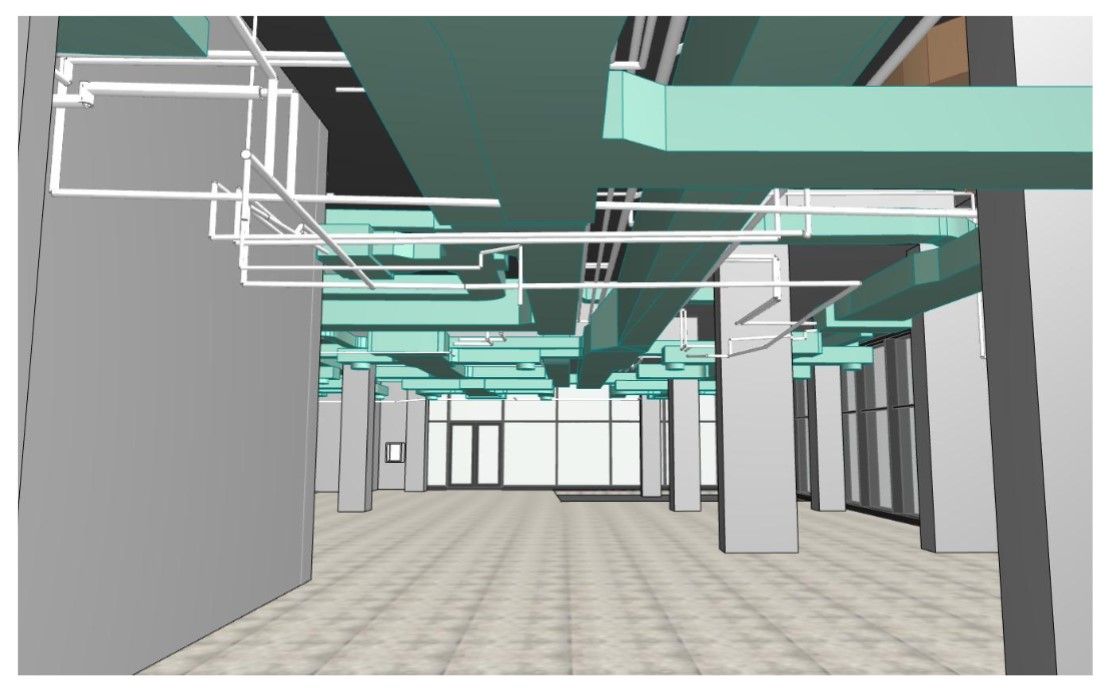
Sprinkler piping is usually the last system to find space above the ceiling, and that is where it runs into ducts, beams, cable trays and light fixtures. ScanM2 builds Revit fire protection models – sprinkler heads, branch lines, mains, risers, valves, standpipes and fire pump equipment – so the system can be coordinated with structure and other MEP trades before anyone cuts pipe on site.
Contact Us Now for a Free Consultation!
We model new fire protection systems from the layout prepared by your fire protection engineer or designer, and we model existing systems from 3D laser scans of the building. The second part is where our background helps: 3D laser scanning is our core work, so we can capture mains, risers and valve assemblies in occupied buildings and turn them into an accurate as-built model for retrofits, tenant improvements and renovation projects.
What We Model
| Component | What is included in the model |
|---|---|
| Sprinkler heads | Pendent, upright, sidewall and concealed heads placed to the design layout, with type, orientation and elevation |
| Branch lines and cross mains | Pipe sizes, slopes where specified, fittings, outlets, drops and sprigs |
| Feed mains and risers | Main routing, riser locations, floor control assemblies, test and drain connections |
| Valves and devices | Control valves, check valves, alarm valves, dry pipe and pre-action valve assemblies, flow and tamper switch locations |
| Standpipes and hose connections | Standpipe risers, hose valves and fire department connections |
| Fire pump and water supply | Fire pump, jockey pump, controllers, backflow preventers, tanks and connection to the water service |
| Hangers and supports | Hanger and support locations where they are needed for coordination |
| Annotation | Pipe tags, sizes and elevations, head and valve schedules on sheets |
Wet, dry, pre-action and deluge systems are modeled with the components shown in the design documents. We use native Revit fire protection systems and families with correct pipe connectors, so the model can be scheduled, filtered by system and exported to coordination software. If your project needs specific manufacturer content, we can build it as part of our Revit family creation services.
Who Does the Design, and What We Do
Fire sprinkler design – system type, hazard classification, head spacing and hydraulic calculations – is the responsibility of the fire protection engineer of record or the licensed sprinkler designer, working to NFPA 13 and the local code. ScanM2 does not replace that role. We build the BIM model from the engineer’s layout and calculations, keep pipe sizes and head positions as designed, and flag any conflict we find during coordination so the designer can decide how to resolve it.
This split keeps responsibilities clear: the engineer owns the design, and we make sure the design fits the building in 3D.
New Design or Existing Systems From Laser Scans
New construction. We convert 2D fire protection drawings, CAD plans or a design-intent Revit model into a detailed model that can be coordinated with the rest of the building. Architectural and structural models are linked so ceiling heights, beam depths and shafts are respected.
Existing buildings. In retrofits, tenant improvements and system upgrades, the existing sprinkler mains and risers are rarely shown correctly on old drawings. We scan the building with FARO terrestrial laser scanners (typical accuracy ±2–3 mm), register the point cloud and model the existing fire protection system together with the structure and other services that limit new routing. Scanning can be done in occupied buildings, floor by floor or area by area, so normal operations are not interrupted.
The result is an as-built model that shows where existing pipes really are – including elevations above ceilings and in mechanical rooms – so the new design can tie in at the right points. We do not have local offices: our team travels quickly to any US state, or works remotely from your own point clouds. More about this workflow on our point cloud to BIM and as-built MEP drawings pages.
Coordination With Structure and Other MEP Trades
Fire protection piping must keep clearances from ducts, cable trays, plumbing, lighting and structural members, and sprinkler heads must not be blocked by obstructions. We link the fire protection model with architectural, structural, HVAC, plumbing and electrical models and check the routing in Revit and Navisworks.
- conflicts between mains and ductwork, beams and other piping are found and reported with clear viewpoints;
- head positions are checked against ceiling grids and lighting layouts;
- routing changes are made in agreement with the designer and other trades;
- the coordinated model is exported as NWC/NWD for your coordination meetings.
For whole-building coordination see our MEP BIM coordination services and BIM clash detection services. Related disciplines: Revit plumbing design, Revit mechanical design and electrical BIM services.
Level of Development
The level of development is agreed per project, based on how the model will be used.
| LOD | Typical use for fire protection |
|---|---|
| LOD 200 | Approximate mains and riser locations for early space planning |
| LOD 300 | Mains, branch lines and heads at designed sizes and positions for design coordination |
| LOD 350 | Adds hangers, valve assemblies and interfaces with other systems for detailed coordination |
| LOD 400 | Fitting-level detail for detailing and as-built documentation, where the project requires it |
Most fire protection coordination models are produced at LOD 300–400. If you work to a BIM execution plan, we follow its LOD definitions and naming.
What We Need From You
- fire protection drawings or the design layout (DWG, PDF or Revit), with hydraulic calculation results or pipe sizes if available;
- architectural, structural and other MEP models or drawings for coordination;
- your Revit version, template, BIM execution plan and family standards, if you have them;
- for existing systems: access to the building for laser scanning, or your existing point cloud (E57, RCP/RCS or other common formats).
If information is missing or unclear, we send a list of questions before modeling.
What You Receive
| Deliverable | Details |
|---|---|
| Revit model | RVT in your Revit version, fire protection systems separated and named per your standards |
| Coordination files | NWC/NWD exports for Navisworks, clash reports with viewpoints when coordination is in scope |
| Open BIM | .ifc export for teams using other software |
| 2D drawings | DWG/PDF plans, sections and riser diagrams generated from the model |
| Schedules | Sprinkler head, valve and pipe schedules from the model |
| Point cloud (existing buildings) | Registered point cloud in E57 or RCP for reference |
How a Fire Protection BIM Project Works
- Review. We review the design documents, existing models or scan requirements and agree the scope, LOD and deliverables.
- Laser scanning (existing buildings). We scan the areas where the existing system must be captured and register the point cloud.
- Modeling. We build the fire protection model from the design layout or the point cloud, using your template and standards.
- Coordination. We link other discipline models, run clash checks and resolve routing with the designer and other trades.
- Quality check. Pipe sizes, connections, systems and annotation are checked against the source documents before delivery.
- Delivery and updates. You receive the agreed files; design changes can be incorporated as the project develops.
Who This Service Is For
- Fire protection contractors – coordinated models and drawings that show the system in the context of the building, ready for detailing and installation planning.
- MEP engineers – fire protection modeled alongside HVAC, plumbing and electrical so the whole MEP package is coordinated.
- General contractors – a fire protection model that can join the federated coordination model with the other trades.
- Building owners and facility managers – as-built models of existing fire protection systems for renovations, upgrades and long-term maintenance planning.
Fire protection modeling is part of our wider Revit MEP BIM services, Scan to BIM and Revit BIM modeling work.
FAQ
What is fire protection BIM modeling?
Do you design sprinkler systems or perform hydraulic calculations?
Can you model an existing sprinkler system?
Can you scan an occupied building?
Which LOD do you model fire protection to?
Do you coordinate fire protection with other trades?
Which file formats do you deliver?
What do you need to start?
Discuss Your Fire Protection Model
Send us your fire protection drawings, existing models or a description of the building you need scanned. We review the scope, ask questions where information is missing and send a proposal for the modeling and coordination work.

