

LOD 500 BIM Modeling Services
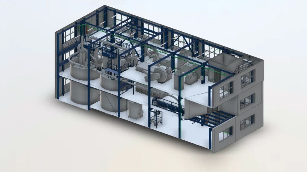
A LOD 500 model is the version of your building that has been checked against the building itself. Not the design model updated with a few redlines, and not a model with more detail than the others – a model where walls, slabs, ducts, pipes and equipment have been compared with what is actually on site, and where the information facility teams need is attached to the right objects. ScanM2 builds LOD 500 as-built BIM models in Autodesk Revit from 3D laser scans, so the model your operations team receives reflects the building they actually maintain.
Contact Us Now for a Free Consultation!
We are clear about one thing from the start: “LOD 500” is often used as a label for “the most detailed model.” That is not what it means, and a model is only as useful for operations as the verification behind it. Below we explain what we check, how we check it, and what information we need from you.
What LOD 500 Really Means
LOD (level of development) describes how complete and reliable each model element is. LOD 100 to 400 describe a model’s progress through design and construction, up to fabrication-level detail. LOD 500 is different: in the BIMForum LOD Specification it is not a higher level of geometry or information, but a statement that the elements have been verified in the field. A LOD 500 duct does not need more detail than a LOD 300 duct – it needs to be where the duct really is, at the size it really has. For the full scale with examples, see our article BIM LOD Levels Explained.
| Question | LOD 300 / 400 | LOD 500 |
|---|---|---|
| What does it describe? | Design or fabrication intent | The building as it exists and was checked |
| Where does the geometry come from? | Design documents, submittals, shop data | Field measurement – in our case, a laser scan |
| Is more detail required? | LOD 400 adds fabrication detail | No; the level of detail is agreed per element type |
| Who uses it? | Designers, contractors, fabricators | Owners, facility managers, renovation teams |
Two consequences follow. First, you choose what to model: a LOD 500 model of a hospital can include every plant room and riser in detail and keep office floors simple, as long as what is modeled is verified. Second, an element that cannot be verified – a pipe inside a wall, a cable in a closed ceiling – should not be called LOD 500. We mark such elements clearly instead of presenting them as checked.
If your project needs fabrication-level detail for new installations rather than an as-built record, see our LOD 400 BIM modeling services.
How We Verify the Model Against the Building
Verification is the part that makes a model LOD 500, so it is built into our process rather than added at the end.
- Laser scanning. We scan the agreed areas with FARO laser scanners. Typical accuracy of the registered point cloud is ±2–3 mm, which is more than enough to confirm positions of walls, openings, ducts, pipes and equipment. We travel to sites in any US state, or we work with point clouds your team or your scanning provider already has.
- Modeling from the point cloud. The Revit model is built directly on the scan, not traced from old drawings. Existing drawings are used only to identify systems and for parts the scanner cannot see.
- Deviation check. A second specialist compares model elements with the point cloud and records any element that sits outside the agreed tolerance.
- Status of every element. Each element carries a parameter showing whether it was verified by scan, taken from documents, or assumed. Facility teams can filter the model and see at a glance what has been checked on site.
Why a laser scan rather than tape measurements or redlines? Because a scan captures the whole space at once, including ceiling voids, plant rooms and shafts that rarely appear correctly on drawings. More about the capture side in our Scan to BIM services and 3D laser scanning services.
Data for Operations and Maintenance
Geometry tells a facility team where things are. Data tells them what they are. In a LOD 500 model for facility management, we attach operational information to equipment and spaces as Revit parameters, following your naming and your CAFM or CMMS requirements.
| Data group | Examples of parameters |
|---|---|
| Identification | Asset tag, equipment type, system, room and level |
| Product | Manufacturer, model, serial number, capacity or rating |
| Maintenance | Service interval, responsible contractor, link to the O&M manual |
| Warranty | Installation date, warranty start and end |
| Spaces | Room name and number, area, department, finish types |
| Status | Verified by scan / from documents / assumed |
We fill these parameters only from information you provide or from what is visible on site, such as a nameplate in a scan photo. We do not invent serial numbers or service intervals. If your organization uses a specific data template or naming standard, send it to us and we will set the parameters up to match it. If you do not have one yet, we propose a simple parameter set you can extend later.
What We Need From the Owner
The quality of the data in the model depends on the documents behind it. Before modeling starts, we ask for:
- Equipment schedules and nameplate data – manufacturer, model and serial number for the equipment you want in the model.
- O&M manuals and equipment data sheets – service intervals, spare parts and maintenance requirements.
- Warranty information – installation and warranty dates where they matter for your team.
- Existing drawings and models – to identify systems and hidden elements.
- Your data template or asset list – the parameters, codes and naming your CAFM or CMMS expects.
- Access – plant rooms, risers and ceiling areas we need to scan, with any site rules.
If some of this is missing, we still deliver verified geometry and mark the empty fields, so your team knows exactly what to complete.
What We Model
- Architecture – walls, floors, ceilings, doors, windows, stairs, rooms and areas. See Revit architecture modeling.
- Structure – columns, beams, slabs and openings visible in the scan. See Revit structural modeling.
- MEP – ductwork, piping, equipment, panels, cable trays and fire protection, with the systems your team maintains. See MEP BIM modeling.
- Equipment families – when manufacturer content is missing, we build Revit families with connectors and parameters for your data. See Revit family creation services.
Industrial and oil & gas facilities – piping, skids and equipment – can be modeled from point clouds in the same way.
What You Receive
| Deliverable | Details |
|---|---|
| Revit model (RVT) | LOD 500 elements in the agreed areas, in your Revit version and template |
| Verification status | Parameter on each element: verified by scan, from documents or assumed |
| Operations data | Equipment and space parameters filled from your documents |
| Schedules | Equipment, room and asset schedules from model data, exportable to spreadsheets |
| .ifc export | For CAFM, CMMS and other BIM software. See IFC file format explained |
| Point cloud | Registered scan data, linked to the model for future reference |
| Drawings | Plans, sections and 3D views as DWG or PDF on request |
| Open items list | Missing documents, empty fields and elements that could not be verified |
How This Page Fits With Our Other Facility Services
If you need floor plans and drawings for property management rather than a data-rich model, see our as-built services for facility management. If your first step is capturing the building, see laser scanning for facility management. For the wider picture of how as-built models are used in operations and renovation, read How As-Built BIM Models Support Facility Management.
Who This Service Is For
- Owners and facility managers taking over a building whose handover documents do not match reality.
- Healthcare, campus and corporate real estate teams that need asset data tied to real locations.
- Operators planning upgrades who want one verified model as the base for future projects.
- Design and contractor teams asked to deliver a LOD 500 record model at handover.
FAQ
What is a LOD 500 BIM model?
Is a LOD 500 model more detailed than LOD 400?
How do you verify the model against the building?
Can you create a LOD 500 model from drawings and redlines only?
What operations data can you add to the model?
What do you need from us to add equipment data?
Can the model be used in our CAFM or CMMS system?
Do you scan buildings outside your area?
Send Us Your Project
Tell us which building and areas you need, which systems matter for your team, and what documents you already have – equipment lists, O&M manuals, drawings or a point cloud. We review the information, suggest what to verify and which data to attach, and send a quote based on the scope.

