

As-Built Drawings for Hydroelectric power station
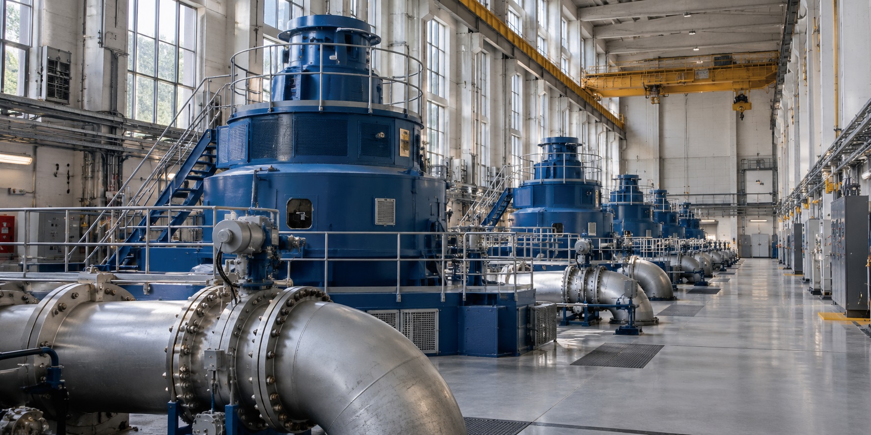
Hydroelectric power stations operate for decades, often undergoing multiple equipment replacements, structural modifications, and technical upgrades. Over time, original construction drawings may no longer represent the actual configuration of the powerhouse, machinery, piping, and supporting infrastructure.
ScanM2 provides As-Built Drawings Services for Hydroelectric Power Stations, preparing accurate technical drawings that document existing building geometry, equipment locations, structural elements, and engineering installations. Our documentation supports plant modernization, reconstruction, maintenance planning, and the development of new engineering designs.
Contact Us Now for a Free Consultation!
Why Hydroelectric Facilities Need Updated As-Built Drawings
Existing hydroelectric facilities rarely remain unchanged throughout their operating lives. Turbines and generators may be replaced, equipment foundations modified, auxiliary systems rerouted, and access platforms reconstructed. However, these changes are not always incorporated into the original drawing archive.
When engineering teams rely on outdated documentation, they risk designing around incorrect dimensions, missing installations, or equipment positions that have changed.
Updated as-built drawings establish a measured reference for the existing facility, helping engineers understand current conditions before planning modifications.
What As-Built Documentation Can Include
The drawing package depends on the project area, available measurements, and intended engineering use. For hydroelectric power stations, documentation may include the following types of drawings.
Powerhouse Floor Plans
Measured floor plans document the layout of powerhouse levels, including walls, columns, structural openings, circulation routes, technical rooms, and the positions of relevant equipment.
These plans help engineers evaluate available space for new machinery, maintenance access, and alterations to existing building layouts.
Building Sections and Elevations
Sections and elevations show vertical relationships between floors, structural elements, equipment foundations, roof structures, platforms, and technical installations.
They are particularly important when modernization involves tall equipment, overhead lifting arrangements, or changes to structural openings.
Turbine Hall and Generator Layouts
Equipment layout drawings record the measured positions and external dimensions of turbines, generators, and surrounding installations within the relevant areas.
Depending on the scope, drawings may also show equipment foundations, accessible connection points, nearby structures, and spatial constraints affecting future work.
Piping and Mechanical Installation Drawings
Hydroelectric facilities contain auxiliary piping, valves, pumps, cooling installations, and other mechanical systems. Measured drawings can document their accessible routing and spatial arrangement where this information is needed for engineering work.
These drawings are useful when planning equipment replacement, piping modifications, or work in congested technical rooms.
As-Built Drawings for Turbine and Generator Replacement
Replacing generating equipment requires precise information about the space surrounding the existing installation. The engineering team may need to verify equipment foundation dimensions, distances to structural elements, floor elevations, and access openings.
As-built drawings provide the dimensional reference needed to assess these conditions and develop preliminary installation solutions.
Where detailed three-dimensional coordination is required, the measured information can also support BIM Modeling Services for Hydroelectric Power Stations.
Documenting Equipment Foundations and Structural Interfaces
Equipment foundations are critical interfaces between mechanical installations and the building structure. During modernization, engineers may need to compare the existing foundation geometry with the requirements of replacement equipment.
Measured documentation can record accessible foundation outlines, elevations, openings, adjacent structural elements, and other visible features relevant to the project.
Concealed reinforcement, embedded anchors, and internal foundation conditions cannot be established from surface measurements alone. These details require suitable technical documentation or additional investigation.
As-Built Documentation for Technical Galleries and Service Areas
Technical galleries, service corridors, and underground equipment areas often contain closely spaced installations and limited working space. Accurate drawings can help maintenance and design teams understand the layout before entering or modifying these areas.
Documentation may cover corridor dimensions, access points, equipment positions, piping routes, structural features, and changes in floor elevation.
For projects involving restricted or operational areas, the survey scope and access conditions must be coordinated with the facility operator.
Drawing Existing Penstocks and Hydraulic Structures
Hydroelectric power stations may include penstocks, intake structures, discharge areas, and other hydraulic infrastructure whose geometry affects reconstruction and maintenance projects.
Where suitable survey access and source data are available, as-built drawings can document the visible geometry of these structures, their elevations, relevant dimensions, and interfaces with adjacent construction.
Submerged or inaccessible portions of hydraulic infrastructure require additional measurement methods or verified existing records.
Creating As-Built Drawings from 3D Laser Scanning
Large industrial spaces and densely arranged equipment can be difficult to document using isolated manual measurements. Terrestrial laser scanning captures extensive geometric information that can be used to prepare measured plans, sections, and elevations.
Our 3D Laser Scanning Services for Hydroelectric Power Stations provide point cloud data representing accessible surfaces and installations.
Once registered and prepared, the point cloud becomes a geometric reference for drafting existing structures, equipment positions, and relevant engineering features.
From Point Cloud Measurements to CAD Drawings
Producing useful as-built drawings involves more than tracing visible surfaces. The drafting team must interpret the measured geometry, identify the relevant elements, establish drawing conventions, and represent the information at an appropriate level of detail.
For large or complex survey datasets, Point Cloud Processing Services for Hydroelectric Power Stations help prepare the measurement data before CAD documentation begins.
The final drawings should clearly distinguish documented geometry from any information derived from external records or requiring further verification.
As-Built Drawings for Hydroelectric Powerhouse Reconstruction
Powerhouse reconstruction can involve new openings, modified floor layouts, changes to access platforms, structural alterations, and the installation of additional technical systems.
Measured plans and sections allow designers to work with the current building configuration rather than relying exclusively on historical documentation.
They can also provide a consistent reference for coordinating architectural, structural, and mechanical design tasks across different engineering teams.
Updating Historical Drawings with Current Measurements
Many older hydroelectric power stations retain archives of original construction drawings and subsequent modification records. These documents remain valuable, but their accuracy should not be assumed without checking relevant existing conditions.
New measurements can be used to verify critical dimensions and update drawing sets for the areas affected by the project.
Where original records are incomplete, measured drawings can establish a new baseline for accessible parts of the facility.
Do You Need 2D Drawings or a BIM Model?
The appropriate documentation format depends on the intended use. Two-dimensional drawings are often sufficient for floor layouts, sections, equipment positioning, and conventional design documentation.
A BIM model becomes more valuable when the project requires coordinated three-dimensional representation of multiple engineering systems or repeated spatial analysis.
For projects requiring an existing-condition BIM model developed specifically from survey data, see our Scan to BIM Services for Hydroelectric Power Stations.
Our As-Built Documentation Workflow
We organize the documentation process around the engineering questions that the drawings need to answer.
- Define the drawing scope. Identify the facility areas, required drawing types, measurement requirements, and intended use.
- Review existing documentation. Examine available plans, equipment drawings, and other technical records.
- Collect or receive survey data. Obtain the measurements needed to document accessible existing conditions.
- Prepare geometric references. Register and organize point clouds or other survey information as required.
- Develop CAD drawings. Produce the agreed plans, sections, elevations, and equipment layouts.
- Check drawing accuracy. Compare documented geometry with available measurement data and project requirements.
- Deliver the drawing package. Provide the agreed files and supporting documentation.
Typical As-Built Drawing Deliverables
Depending on the facility and project objectives, the documentation package may contain:
- Measured powerhouse floor plans
- Building elevations and cross-sections
- Turbine hall and generator equipment layouts
- Equipment foundation and structural interface drawings
- Technical gallery and service room plans
- Selected piping and mechanical installation drawings
- CAD files and PDF drawing sets
Accuracy and Scope of Hydroelectric As-Built Drawings
The achievable drawing accuracy depends on the survey method, measurement quality, site accessibility, and characteristics of the documented elements.
Before starting the project, it is important to establish which dimensions require verification, what drawing scale or detail is appropriate, and which areas can be measured safely.
As-built drawings represent the conditions documented by the available measurements and source records. They should not be interpreted as verification of concealed systems, internal equipment geometry, or structural capacity.
Reliable Drawings for Hydroelectric Modernization
Accurate as-built documentation reduces uncertainty when planning changes to an operating hydroelectric facility. Measured drawings help engineering teams understand existing dimensions, identify relevant spatial constraints, and prepare modifications using a consistent technical reference.
ScanM2 prepares project-specific as-built drawing packages for industrial and energy infrastructure, with the scope and level of detail adapted to the facility and planned engineering work.

