

Point Cloud Alignment and Coordinate Systems
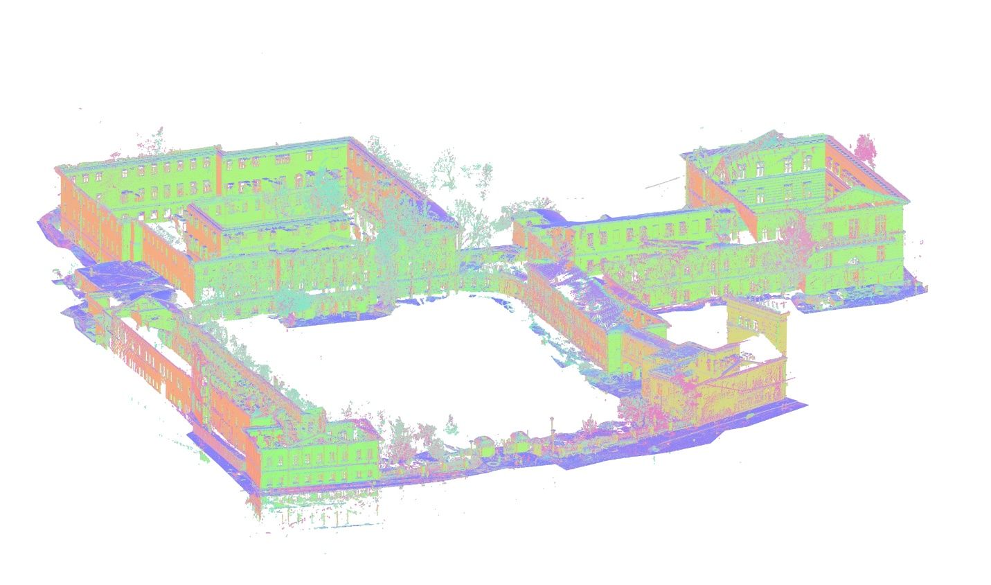

A registered point cloud is a single, consistent 3D dataset, but that does not tell you where it sits. Unless someone decides otherwise, the cloud keeps the origin and orientation of the first scanner position: X and Y start wherever the tripod stood, the Y axis points wherever the scanner happened to face, and zero elevation is the height of the scanner head. That is fine for viewing the data. It is not fine when the cloud has to line up with a site survey, an architect’s existing drawings, a civil model or a Revit model that other consultants will link.
Point cloud alignment to a coordinate system is the step that answers “where is this cloud in the project and in the world?”. It is different from registration, which joins individual scans to each other; we explain that step in how point cloud registration works. This article covers what comes after: choosing a coordinate system, tying the cloud to control points, keeping units and elevations consistent, placing the cloud correctly in Revit, and avoiding the errors that make a model end up in the wrong place.
Registration vs Alignment
The two steps are easy to confuse because both are often described as “aligning scans”.
- Registration answers: do all scans fit together? Its result is one cloud whose internal geometry is consistent.
- Alignment, or georeferencing when real-world coordinates are used, answers: where does that cloud sit? Its result is the same cloud moved and rotated into a chosen coordinate system.
A cloud can be perfectly registered and still be in the wrong place, rotated by a few degrees or set at the wrong elevation. The reverse is also true: correct coordinates on a few targets do not fix a poorly registered cloud. Both steps need to be checked separately.
Three Kinds of Coordinate Systems
Most projects use one of three systems. The choice should be made before scanning, because it decides whether survey control is needed on site.
| System | What defines it | Typical use | What to watch |
|---|---|---|---|
| Scanner (arbitrary) | Origin and orientation of the first scan position | Quick documentation, a single room or object, data that will not be combined with other files | Nothing else will line up with it; every consultant has to move it manually |
| Local or project grid | A point chosen on the building (grid A/1, a column center, a corner) and an axis along a main wall or grid line; elevation such as finished floor = 0 or 100 ft | Renovation and interior projects where the cloud must match existing drawings or a design model | The origin and axes must be written down and agreed by everyone; “the corner” can mean different things |
| State plane, UTM or another mapping system | Official projected coordinate system plus a vertical datum (for example NAVD88) | Sites, campuses, new construction next to existing buildings, projects shared with civil engineers and surveyors | Large coordinate values, grid vs ground distances, units (US survey foot vs international foot), vertical datum |
Many projects use a combination: the Revit model works in a local project grid, and that grid is tied to state plane coordinates through a known point and a rotation. Revit supports this directly with its Survey Point and Project Base Point, discussed below.
How a Point Cloud Is Tied to Control Points
To place a cloud in a known coordinate system, the cloud needs to contain points whose coordinates in that system are known. These are control points.
Who provides the control
On projects that need official coordinates, control is established by a licensed surveyor, usually with GNSS receivers and a total station. The surveyor sets marks on site and provides their coordinates in the agreed system, with the datum and units stated. On interior projects, control can also come from existing reference points in the building or from an existing CAD or BIM model of the same building.
What happens on site
Targets (checkerboards or spheres) are placed over or next to the control marks, so that the scanner captures them with good geometry. Control should surround the scanned area, not sit in one corner, and it should appear at different heights where elevation matters. We describe how this fits into the field routine in our laser scanning workflow from site to point cloud.
A minimum of three well-spread control points is needed to define position and rotation in 3D. In practice, more points are better: the extra ones act as checks. A good habit is to keep one or two control points out of the transformation and use them only to verify the result. If the cloud lands correctly on points that were not used to compute the alignment, you can trust the result much more than a simple software report.
What happens in the office
In registration software, such as FARO SCENE, the target centers in the cloud are matched to the surveyed coordinates. The software computes the best-fit transformation and reports residuals: how far each target lies from its surveyed position after alignment. Large or uneven residuals usually mean a wrong point ID, a disturbed mark, a units mix-up, or a target captured at a poor angle.
How accurate is the alignment
The cloud’s internal geometry depends on the scanner and registration; our FARO scans have a typical accuracy of ±2–3 mm. How well the cloud fits the coordinate system also depends on the quality of the control itself, the number and spread of control points and how they were captured. The two figures should be reported separately. For more on the measurement side, see 3D laser scanning accuracy.
When control is not needed
Not every project needs survey control. A cloud used for an interior fit-out, a single floor of an existing building or a piece of equipment can be aligned to a local project grid without any surveyed points. The question to ask is simple: will this data ever be combined with a site survey, a civil model or a file in real-world coordinates? If yes, plan control before the scanning visit, because adding it later usually means returning to site.
State Plane Coordinates: Practical Traps
State plane coordinate systems are the usual choice for US projects that involve a site survey. They work well, but they bring a few details that cause most alignment errors. For site work where the cloud also produces terrain and surface data, see our laser scanning topographic surveys.
Grid distances and ground distances
A state plane system projects the curved earth onto a flat grid. As a result, a distance measured on the grid is slightly different from the same distance measured on the ground. The difference is described by a combined scale factor, which depends on location and elevation. A laser scanner measures ground distances, and so does anyone with a tape measure in the finished building.
If a cloud is placed in grid coordinates without considering this, distances in the cloud may no longer match distances on site. The usual solutions are to work in a local ground system tied to state plane through a known point, rotation and documented scale factor, or to agree with the surveyor exactly how the scale factor is applied. Either way, the choice should be written into the project’s coordinate notes.
US survey foot vs international foot
Older state plane coordinates in many states are expressed in US survey feet, while most software uses the international foot. The two differ by about two parts per million. That sounds negligible, but state plane coordinates are often in the millions of feet, so the wrong foot can shift the whole dataset by a few feet. Always confirm which foot the survey uses.
Vertical datum
Horizontal coordinates are only half of the system. Elevations can refer to an official vertical datum such as NAVD88, to an older datum, to a site benchmark or to a project elevation such as first floor = 100 ft. GNSS receivers measure heights above the ellipsoid, which differ from orthometric (sea-level based) heights until a geoid model is applied. A model that sits at the right X and Y but several feet too high or too low is a common result of mixing these.
Units and Formats
Unit errors are simple but frequent. A few rules help:
- State the units of every file: meters, international feet or US survey feet.
- Remember that formats differ. E57 stores coordinates in meters; CAD and Revit files may be set up in feet and inches.
- Check one known distance after every import. If a wall that should be 30 feet long measures about 9 or about 98, the file was read in the wrong units.
- Keep coordinate order clear. Surveyors often list northing before easting, while most software expects X (easting) first. Swapped values put the cloud in the wrong place without any error message.
Point Clouds in Revit: Survey Point, Project Base Point and Internal Origin
Revit has three reference points, and most point cloud placement problems come from mixing them up. Our scan to Revit services use the same logic on every project.
| Point | What it is | How it is used with point clouds |
|---|---|---|
| Internal Origin | Revit’s fixed internal zero; it cannot be moved | Geometry should stay reasonably close to it; Revit warns when elements are placed very far away, and graphics and precision can suffer |
| Project Base Point | The project’s own reference, usually a building corner or grid intersection | Defines project coordinates: dimensions and spot coordinates relative to the building |
| Survey Point | A real-world reference, such as a control point with known state plane coordinates | Defines shared coordinates, the system that lets Revit, CAD and point cloud files line up |
Linking the cloud
When a point cloud (RCP or RCS) is linked into Revit, the positioning option decides where it lands:
- Center to center places the cloud’s center at the model’s center. It is useful only for a quick look; it ignores all coordinates.
- Origin to internal origin places the cloud’s own origin at Revit’s internal origin. This works when the cloud and the model were both set up around the same local zero.
- By shared coordinates places the cloud according to the model’s shared coordinate system. This is the right choice when the cloud is in state plane or another real-world system and the Revit model’s Survey Point has been set to match.
A typical workflow for a georeferenced project is: the surveyor provides control in the agreed system; the cloud is aligned to that control during processing; the shared coordinates of the Revit model are set from the same control, often by linking a CAD file of the control points and acquiring its coordinates; and only then is the cloud linked by shared coordinates. Modeling starts after a check that the cloud and the control lie on top of each other in plan and in section.
Keeping geometry near the internal origin
State plane coordinates are large numbers. If a cloud with such coordinates is linked origin to internal origin, the building may end up miles from Revit’s zero. The solution is not to move the building far away, but to keep the model geometry near the internal origin and let the Survey Point carry the real-world offset and rotation. Shared coordinates exist exactly for this purpose.
IFC export
When the model is delivered as .ifc, the coordinate setup travels with it if export settings are chosen correctly: the coordinate base (shared coordinates or project base point) and, in newer versions, the coordinate reference system. Open the exported file in a viewer and check that it lands where expected. We explain the format itself in IFC model file format explained.
Common Alignment Errors
| Error | Typical symptom | How to check |
|---|---|---|
| Cloud linked center to center or origin to origin by mistake | Cloud and model do not overlap at all, or overlap only by chance | Compare known control points in the cloud with the Survey Point and with the surveyor’s list |
| Wrong units | Building is about three times too large or too small | Measure a known distance right after import |
| US survey foot vs international foot | Whole dataset shifted by a few feet, shape correct | Confirm the foot definition in the survey notes |
| Northing and easting swapped | Cloud lands far away or mirrored across the site | Check coordinate order of the control list |
| Wrong vertical datum or project elevation | Plan position correct, elevations off by a constant value | Compare floor elevations with a known benchmark |
| Grid vs ground scale not agreed | Small, growing length differences on long buildings and sites | Compare a long measured distance with the grid distance |
| Disturbed or misidentified control point | One large residual, the others small | Recheck point IDs; use check points not included in the fit |
| Survey Point moved while clipped or unclipped by accident | Shared coordinates change unexpectedly between model versions | Record base point values and check them at each issue |
Most of these errors share one cause: the coordinate decisions were made by different people at different times and never written down. A one-page coordinate note at the start of the project prevents most of them.
What Should Come with an Aligned Point Cloud
When you receive a point cloud from us or from any scanning provider, or send your own cloud for modeling, the files should come with a short description of the coordinate setup:
- Coordinate system name, including zone for state plane, and the horizontal units with the foot definition.
- Vertical datum or project elevation, and what zero means on this project.
- Local origin and rotation if a project grid is used, with its relation to real-world coordinates.
- Scale factor approach: grid or ground.
- Control point list with IDs and coordinates, and which points were used as checks.
- A registration and alignment report with residuals.
- File formats delivered (for example E57, RCP) and the Revit positioning option to use when linking.
If any of these are unknown, the cloud can still be used, but the uncertainty should be clear before modeling starts. We check these items when clients send us existing data; see what makes a point cloud BIM-ready for the full list of what we look at.
FAQ
What is the difference between point cloud registration and alignment?
How many control points are needed to georeference a point cloud?
Can a point cloud be aligned without a surveyor?
Should I link a point cloud in Revit by shared coordinates or origin to origin?
What is the difference between the Survey Point and the Project Base Point?
Why is my point cloud in the wrong place in Revit?
Can you work with a point cloud that is not georeferenced?
Decide Coordinates Before You Scan
Coordinate problems are rarely technical in the end. They come from decisions that were not made early enough or not shared with everyone who uses the data. Agree on the coordinate system, units, vertical datum and control before the scanning visit, record them in a short coordinate note, and check the cloud against control before modeling starts. Then the point cloud, the Revit model, the CAD files and the site survey all stay in the same place. ScanM2 travels to sites in any US state for FARO laser scanning and also works from clients’ existing point clouds, with Revit and .ifc delivery set up in the coordinate system your project needs. Learn more about our scan to BIM services, or send us your project details to discuss the coordinate setup.

ScanM2 Launches ScanTrack: Manage Tasks Directly in a 3D Virtual Tour
18.10.2026
How integrating as-built documentation using advanced 3D scanning and laser scanning technology can revolutionize your real estate marketing strategy. Learn the benefits for agents and ...
Which 3D Laser Scanner Should Architects Choose, and When Is Outsourcing Better?
17.10.2026
How integrating as-built documentation using advanced 3D scanning and laser scanning technology can revolutionize your real estate marketing strategy. Learn the benefits for agents and ...

INTERGEO: How Laser Scanning Is Becoming a Foundation for Management and Decision-Making
24.09.2026
ScanM2 once again took part in INTERGEO, which was held in Munich this year. For us, the event is an opportunity to meet with partners, ...

How 3D Laser Scanning Measures Floor Flatness and Levelness
22.09.2026
Floor flatness and levelness can directly affect equipment installation, racking systems, automated material handling, production lines, flooring systems, and other construction activities that depend on ...

