

3D Laser Scanning for Electric Power Transmission
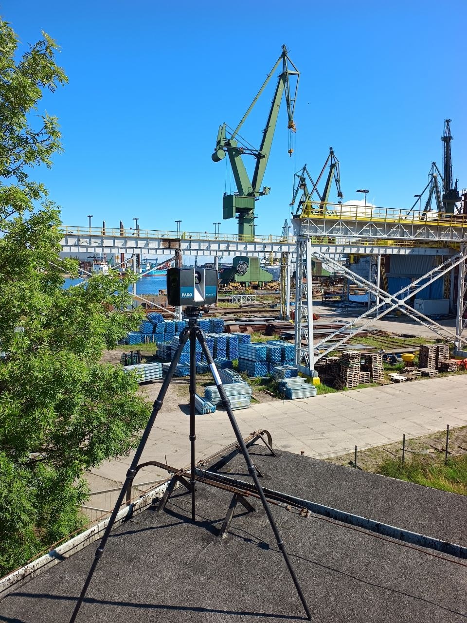
Transmission lines extend across changing terrain, road crossings, industrial sites and densely developed areas. Their structures are exposed to weather, ground movement and successive modifications, while older drawings may not accurately describe the present arrangement. When a line is upgraded, engineers need more than the nominal dimensions of a tower: they need dependable spatial information about the structures, surrounding obstacles and accessible parts of the corridor.
ScanM2 provides 3D laser scanning services for electric power transmission, capturing measurable geometry of transmission towers, support structures, foundations and selected corridor features for engineering documentation and modernization planning. The survey scope and scanning method are adapted to the terrain, required detail, available access and intended deliverables.
Contact Us Now for a Free Consultation!
A 3D survey can establish a common geometric reference for design teams. It does not, by itself, determine the electrical or structural safety of a line, and the measurement of energized conductors requires particular care in both field planning and subsequent interpretation.
Transmission Infrastructure Is a Linear Survey Problem
Unlike a compact industrial building, an overhead transmission route may cover many kilometers and pass through locations with very different visibility and access conditions. A scanning strategy suitable for a tower foundation is not necessarily suitable for a long span over a valley or highway.
Projects therefore begin by identifying the engineering question. A tower reinforcement study may require detailed steel geometry at a limited number of locations. A corridor modernization project may prioritize the relationship between support positions, terrain, vegetation and nearby infrastructure. A connection upgrade may need precise information around selected terminal structures and adjacent facilities.
The choice between terrestrial laser scanning, mobile mapping, aerial LiDAR or a combined survey approach depends on those objectives. These technologies offer different coverage, point densities and measurement limitations; they should not be treated as interchangeable.
What Can Be Captured Along a Transmission Line?
Surveyable elements depend on the equipment, viewpoint and site conditions. For a defined section of overhead line, relevant geometry may include:
- Transmission towers and pylons: accessible lattice members, legs, bracing, crossarms and external structural geometry.
- Support bases: visible concrete foundations, pedestals, anchor locations and surrounding ground surfaces.
- Overhead line features: observable conductor and shield-wire positions where the survey method produces adequate measurements.
- Insulator and attachment zones: visible external arrangements that are sufficiently resolved for the agreed purpose.
- Corridor context: terrain, vegetation, roads, buildings, fences and other obstacles relevant to the project.
- Crossings and interfaces: geometric relationships near railways, waterways, pipelines, substations or industrial facilities, where access and survey coverage permit.
Small connection details, concealed components and thin or distant wires may not be captured reliably by a general-purpose terrestrial survey. Such features can require closer-range methods, additional control measurements or verified engineering records.
Start with the Engineering Decision, Not the Scanner
The required survey accuracy should be established from the intended use of the data rather than from a scanner manufacturer’s headline specification. A broad terrain survey and a close-range inspection of a tower base impose different requirements on point spacing, registration and dimensional verification.
For tower modifications
Priority may be given to the geometry of accessible members, bracing intersections, connection zones and the relationship between the structure and its foundation. Detailed fabrication or bolted-connection work may still require direct metrology and structural inspection.
For line-route upgrades
The important information may be the position of towers and the surrounding corridor, including terrain profiles, nearby structures and the geometry of crossings. A coordinated reference system becomes particularly important when measurements extend across several survey sections.
For construction planning
Site access, equipment positioning, work areas and adjacent physical constraints may be captured to support layout studies. The resulting geometry can inform planning, but cannot authorize lifting operations or work near energized lines.
Conductor Geometry Requires Special Interpretation
Conductors are among the most technically sensitive features in an overhead transmission survey. Their observed positions are influenced by temperature, loading, wind and operating conditions. Thin wires can also be sparsely represented in a point cloud because of their diameter, distance and surface characteristics.
A point cloud records an observed geometric state under the conditions of the survey. It does not automatically establish the maximum sag, minimum statutory clearance or future conductor position under design load cases.
Where conductor modeling is required, the project should define how the survey observations will be combined with conductor specifications, environmental data and appropriate electrical and mechanical calculations. Qualified line engineers must validate the resulting clearance assessments.
Crossings, Terrain and the Space Around the Line
The relationship between a transmission line and its environment often drives the survey scope. At road or railway crossings, engineers may need coordinated terrain and infrastructure geometry. Near industrial facilities, the location of buildings, stacks, cranes or other tall objects can influence planning. In vegetated corridors, the distribution of trees and other obstacles may be important for further assessment.
Scanning can provide a measured spatial dataset for these studies, subject to visibility and coverage. It cannot guarantee complete detection of hidden objects or substitute for utility records, legal corridor boundaries or required specialist surveys.
For extensive routes, an aerial LiDAR survey may be more appropriate for corridor-wide coverage, with terrestrial scanning used to capture selected towers, foundations or complex interfaces in greater detail.
Building a Consistent Survey Across Separate Sites
Transmission projects frequently involve survey crews working at different structures or on different dates. Data collected in isolated local coordinate systems can become difficult to combine, especially when the information must be compared with route design models or existing geospatial records.
A project-wide coordinate strategy should therefore be defined before fieldwork. Depending on the site and survey method, this may involve geodetic control, GNSS observations, total-station measurements and suitable registration references.
After capture, individual datasets are registered, checked and organized into a consistent spatial framework. Point Cloud Processing Services for Electric Power Transmission can prepare scan data for downstream CAD and modeling workflows.
Alignment quality should be reviewed using independent control and relevant geometry where available. A visually convincing combined cloud does not necessarily meet the accuracy required for critical engineering interfaces.

How Survey Coverage Is Planned Around Operating Lines
Electrical transmission environments require formal coordination with the facility owner or operator. Site access, approach distances, permitted equipment locations and work procedures must be determined under the applicable safety rules.
Although terrestrial laser scanning is non-contact, the equipment, tripod, operators and associated surveying activities can still be exposed to electrical and physical hazards. A scanning plan must respect authorized exclusion zones and must not assume that non-contact measurement makes work near energized conductors safe.
Survey coverage can also be affected by vegetation, steep slopes, inaccessible land, weather and restricted rights of way. Areas that cannot be measured should be documented as limitations rather than filled with unverified geometry.
Deliverables Depend on the Next Engineering Step
The output of a transmission-line survey is not always a single point cloud. The most useful package depends on how the measurements will be used after capture.
- Registered point clouds: coordinated 3D measurements in agreed exchange formats such as E57, LAS or LAZ, subject to source compatibility.
- Selected survey views: measured elevations, sections or spatial references for tower and corridor review.
- Coordinate documentation: information about the reference system, control and relevant transformation parameters.
- Coverage and quality notes: identified occlusions, uncertain features and survey limitations.
- Modeling-ready datasets: organized point clouds for CAD, BIM or component reconstruction.
When measured geometry must be converted into structured digital objects, Scan to BIM Services for Electric Power Transmission can address the reconstruction of selected existing assets. For coordinated design development and proposed modifications, see BIM Modeling Services for Electric Power Transmission.
From Survey Data to Reconstruction Documentation
A well-defined scan can reduce uncertainty during the early stages of an upgrade. For example, an engineering team assessing a tower modification may use the measured structure as a reference when comparing proposed reinforcement geometry with existing bracing and accessible connection zones.
For projects that require plans, sections or measured records of the existing installation, As-Built Drawings Services for Electric Power Transmission can translate suitable survey information into technical documentation.
When original drawings of selected fittings, brackets or support components are missing, Reverse Engineering Services for Electric Power Transmission may help reconstruct accessible geometry for further engineering assessment.
These workflows have different objectives. Surveying establishes measured spatial information; drafting and modeling interpret that information for specific project needs. Structural verification, electrical design and component approval remain separate engineering responsibilities.
Define the Scope of Your Transmission Survey
To prepare a suitable scope, it is useful to identify the route or structures involved, the purpose of the measurements, available access conditions, existing drawings, preferred coordinate system and required delivery formats. Particular attention should be given to conductor measurements, tower interfaces and crossings where accuracy or coverage is critical.
ScanM2 supports 3D measurement and digital documentation workflows for power infrastructure. Contact our team to discuss the required survey coverage, data quality and outputs for your electric power transmission project.

