

Scan to BIM for Electric Power Transmission
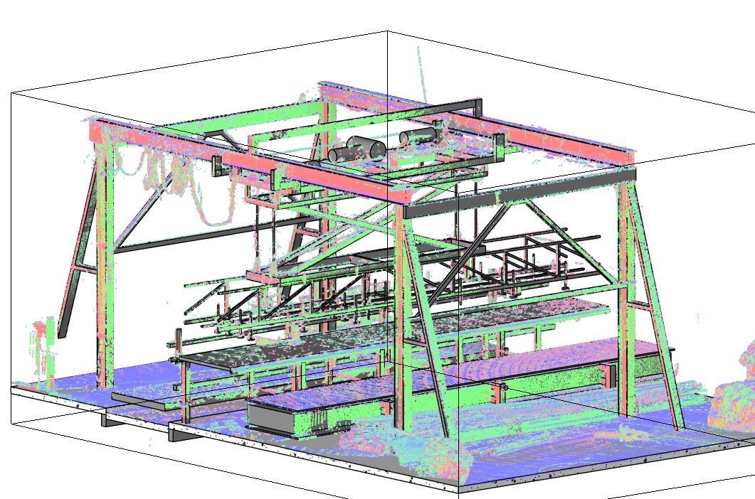
A transmission line is not a single building that can be reconstructed inside one compact model. It is a connected system of towers, conductors, insulator assemblies, foundations and route-specific constraints spread across changing terrain. When the available drawings are incomplete or no longer reflect the installation, engineering teams need a way to relate measured conditions at individual structures to the wider transmission corridor.
ScanM2 provides Scan to BIM services for electric power transmission, converting suitable 3D survey data into structured digital representations of existing overhead line assets. The work can include transmission towers, selected foundations, crossarms, equipment attachment zones and relevant corridor geometry, with the model scope defined around the planned engineering application.
Contact Us Now for a Free Consultation!
The aim is to create a navigable, coordinated existing-condition model rather than simply embed a large point cloud in a design file. Measured geometry, documented asset attributes and unverified assumptions must remain distinguishable throughout the reconstruction process.
One Transmission Route, Many Different Modeling Conditions
A transmission corridor rarely offers uniform source data. One tower may be scanned from several ground positions with good coverage of its legs and lower bracing. Another may be partly obscured by vegetation or terrain. A river crossing may be represented primarily by aerial survey data, while a terminal structure may require close-range measurements of attachment areas.
Consequently, the BIM reconstruction should not impose the same geometric detail on every asset without considering the survey coverage and intended use. A corridor-wide overview can use simplified representations, while selected structures involved in an upgrade may require substantially more detailed modeling.
For long routes, the digital deliverable may consist of coordinated model sections or discipline-specific files rather than one oversized model. A consistent spatial reference allows those sections to be reviewed together.
The Transmission Tower as an Identifiable Digital Asset
Each tower has a role within the line: its position, configuration and relationship to adjacent spans are essential context for the model. Depending on the information supplied, towers can be organized by asset identifier, route section, structural type or other agreed classification.
The geometry reconstructed from measurements may include:
- Tower legs and main members: visible structural alignment and external dimensions where scan density is sufficient.
- Bracing systems: selected diagonal and horizontal members relevant to the engineering task.
- Crossarms: measurable positions and geometry of conductor-supporting arrangements.
- Attachment regions: accessible external geometry around insulator and hardware interfaces.
- Foundation interfaces: visible pedestals, tower feet and surrounding ground conditions.
For lattice towers, representing every bolt, plate and connection is often unnecessary for route-level coordination. If a structural modification depends on a specific joint, that joint should be treated as a separate measurement and modeling requirement. A general point cloud may not resolve its critical details.

What a Span Model Can and Cannot Represent
Conductors connect individual towers into a functioning transmission system, but their geometry differs fundamentally from that of rigid steel members. The observed shape of a suspended conductor depends on temperature, mechanical loading, wind and the conditions at the time of measurement.
A BIM model may include a geometric representation of observed conductor positions when the source survey resolves them adequately. That representation should be identified as an observed state, not as a universal design profile.
Calculated sag curves, clearance envelopes and alternative operating scenarios require suitable line design information and specialist engineering analysis. They should not be generated from a single scan and presented as verified operating limits.
For projects where span behavior is central to the design, the model can serve as a spatial reference for separately validated conductor calculations. The responsibilities and data sources for measured and engineered geometry should be documented.
Route Coordinates Are Part of the Model’s Meaning
A transmission asset model loses much of its value if tower geometry cannot be placed correctly along the route. For a multi-site project, the relationship between survey coordinates, engineering grid systems and local model origins must be defined before reconstruction begins.
Source data may come from terrestrial scans, aerial LiDAR, GNSS-supported surveys or existing design records. Each dataset can have different accuracy characteristics and reference systems. Their integration requires verified transformations and appropriate control.
Before modeling, Point Cloud Processing Services for Electric Power Transmission can support registration, alignment and preparation of the measurements. Where additional capture is needed, 3D Laser Scanning Services for Electric Power Transmission can provide targeted geometric survey data.
Coordinate metadata and known survey limitations should accompany the model so that downstream users can distinguish reliable alignment from approximate positioning.
Corridor Context Without Turning Every Tree into a BIM Object
Transmission line modernization often depends on surrounding conditions: slopes, access routes, vegetation, buildings, crossings and nearby infrastructure. Not all of this information needs to become a detailed parametric BIM element.
For example, terrain may be represented as a surface or linked geospatial reference. Nearby buildings can be modeled as simplified envelopes if their relationship to a proposed modification matters. Vegetation may be retained as classified survey data or simplified spatial objects, depending on the purpose of the project.
This selective approach helps keep the model usable. It also prevents the false impression that every feature within the corridor has been inspected or verified to the same standard.
Reconstruction Decisions: Measured, Documented or Interpreted?
The quality of a Scan to BIM deliverable depends on how confidently each element can be supported. Three categories are useful when reviewing an existing transmission asset model.
Measured geometry
Visible tower members, accessible foundation surfaces and other features may be reconstructed directly from suitable survey measurements within the agreed tolerance. The model should retain a traceable relationship to the source data.
Document-supported attributes
Tower identifiers, conductor specifications, structural member designations and other non-geometric information may be added from reliable asset records or engineering documents. Such information should not be inferred solely from the appearance of the scanned object.
Interpreted or unresolved elements
Concealed foundation geometry, obscured tower connections and poorly measured conductors may need supplementary records, authorized inspection or clearly labeled assumptions. Where evidence is insufficient, omitting an element or marking it as unresolved is preferable to inventing precise geometry.
Model Detail Should Follow the Upgrade Scope
A route-wide inventory, tower strengthening project and foundation replacement program have different information needs. The required level of model detail should therefore be defined for the assets and interfaces involved, not assigned indiscriminately to the whole transmission corridor.
- Route overview: tower positions, simplified structure types, major corridor context and connected line sections.
- Tower modification: selected measured members, bracing arrangements, crossarm geometry and relevant connection regions.
- Foundation intervention: visible support geometry, local terrain and accessible interfaces, supplemented by verified subsurface information where available.
- Crossing assessment: coordinated terrain and obstacle geometry with explicitly identified conductor measurement limitations.
- Multidisciplinary design: asset classification, model organization, agreed coordinates and the information needed for coordination with proposed works.
Project-specific LOD or information requirements can be used to define the expected content, but a high level-of-detail designation does not guarantee survey accuracy or verify concealed structural features.
Integrating Existing Towers with Proposed Reinforcement
Consider a project in which an existing lattice tower is being assessed for a modification. The engineering team may require a measured representation of selected structural members to compare with a proposed reinforcement arrangement.
The Scan to BIM model can provide the existing spatial reference, including accessible steel geometry and relevant surrounding conditions. A separate design model can then represent proposed members or changes. The distinction between existing and proposed elements should remain clear.
This workflow can support geometric coordination and early identification of spatial conflicts. It cannot determine the load capacity of existing members, the condition of bolted connections or the adequacy of the reinforcement. Those matters require structural investigation and calculations by qualified engineers.
Where the work extends into coordinated proposed design, BIM Modeling Services for Electric Power Transmission can support the broader engineering model.
From Model Geometry to Usable Project Records
A structured existing-condition model can be valuable even when the final design is developed in other software. Model views can help teams locate particular towers, review spatial relationships and communicate the boundaries of a planned intervention.
When the project requires measured plans, elevations or sections, As-Built Drawings Services for Electric Power Transmission can provide task-specific CAD documentation. Where selected obsolete brackets, fittings or support interfaces need component-level reconstruction, Reverse Engineering Services for Electric Power Transmission may be appropriate.
Scan to BIM is distinct from both services: it focuses on organizing measured existing assets into a coordinated digital model, with geometric detail and information attributes chosen for the intended engineering workflow.
Delivery Structure and Quality Review
Depending on project requirements, deliverables may include Autodesk Revit models, IFC exchange files, linked survey references and documentation of model coordinates, coverage and assumptions. The exact software and exchange formats should be confirmed before work begins, particularly where route geometry is maintained in specialized power-line or geospatial applications.
Quality review may include comparison of modeled elements with the source point cloud, verification of tower locations, checks on model section alignment and review of element classification. Critical interfaces should be assessed against the agreed geometric tolerances and any additional field measurements required.
A model should also identify areas where scan coverage was insufficient, where geometry was simplified and where information originated from records rather than direct measurement. This makes the deliverable more useful for engineers who were not involved in the original survey.
Prepare an Existing-Condition Model for Your Transmission Project
Effective Scan to BIM for transmission infrastructure starts with a defined route or asset list, an understanding of the proposed engineering work and a clear statement of the required geometric detail. Available survey files, tower records, coordinate information and target software formats help determine a realistic modeling scope.
ScanM2 supports the conversion of suitable survey measurements into organized digital models for power infrastructure. Contact our team to discuss the structures involved, source data quality, model requirements and intended engineering deliverables.

