

Reverse Engineering for Electric Power Transmission
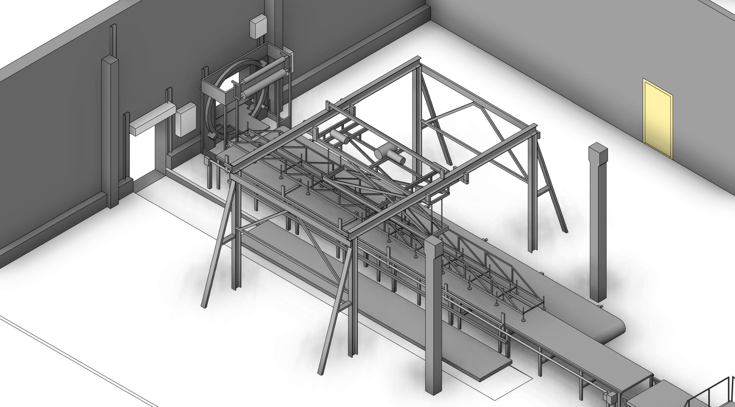
Older transmission structures often remain in service after their original component drawings have been lost, superseded or altered by decades of maintenance. A replacement bracket may need to fit an existing tower, or a proposed modification may depend on the dimensions of a nonstandard connection. In these situations, a generic tower model does not provide enough information.
ScanM2 provides reverse engineering services for electric power transmission, reconstructing the geometry of selected accessible components and interfaces from suitable measurements. The resulting CAD references can support retrofit planning, dimensional comparison and the preparation of engineering documentation for legacy transmission assets.
Contact Us Now for a Free Consultation!
Reverse engineering reconstructs observable geometry; it does not automatically reveal material grade, fatigue condition, heat treatment or structural capacity. Those properties must be established through reliable records, testing and qualified engineering review.
The Challenge Is Usually a Particular Part, Not an Entire Line
A transmission line contains repeated structural systems, but individual supports may have been adapted to local conditions or modified during previous repairs. A replacement part may need to fit a tower whose current geometry differs from the standard drawings. Reconstructing a specific bracket, plate or interface can therefore be more useful than creating an elaborate model of the whole corridor.
The scope should identify the component, the surfaces that control fit and the engineering decision that the reconstructed geometry must support.
Components Commonly Considered for Reconstruction
- Crossarm brackets: visible shapes and connection interfaces associated with conductor-supporting assemblies.
- Gusset and connection plates: accessible outlines, thicknesses and hole patterns when they can be measured adequately.
- Adapter fittings: nonstandard interfaces introduced during past tower modifications.
- Base and support details: exposed steel components at tower-to-foundation interfaces.
- Specialized mounting hardware: accessible components associated with equipment or ancillary attachments.
- Legacy fabricated parts: geometric references for items with incomplete or missing manufacturing drawings.
Some items are not appropriate for reconstruction from general laser scanning alone. Small threads, internal bores, hidden mating surfaces and critical tolerances may require direct contact measurements, close-range metrology or controlled removal of the component.
Begin with the Functional Interfaces
The external silhouette of a component may be easy to scan, but its function depends on specific interfaces: mating faces, bolt-hole centers, bearing surfaces, edge distances and relative orientation. These features should guide the measurement plan.
For a bracket replacement, for example, an engineer may need to know the spacing and alignment of mounting points, the shape of the adjacent tower members and the available installation envelope. A dense point cloud of unrelated surrounding steel does not substitute for accurate measurement of those interfaces.
Choosing a Measurement Method for Legacy Hardware
Terrestrial laser scanning
Useful for capturing the broader tower context, support arrangement and spatial relationship of accessible components. It may not provide sufficient resolution for small holes, fasteners or precision mating features.
Close-range scanning or metrology
May be needed for a detached or safely accessible part with detailed surfaces. The method should be selected according to the required tolerances, surface finish and physical access.
Direct dimensional verification
Critical hole spacing, thickness and fit features may require calipers, gauges, total-station observations or other appropriate metrology. No single method should be assumed sufficient for every component.
When the larger tower arrangement must first be documented, 3D Laser Scanning Services for Electric Power Transmission can provide contextual geometry. Site measurements must follow the operator’s electrical safety requirements and authorized access procedures.
From Point Data to Editable Component Geometry
The reconstruction process typically starts with evaluating the measurement quality and isolating the relevant component. Where needed, Point Cloud Processing Services for Electric Power Transmission can prepare and organize the measured data.
The component can then be reconstructed as CAD surfaces or solids, with dimensions tied to supported measurements. Repetitive or symmetrical features may help interpretation, but inferred geometry must be distinguished from directly verified geometry.
The result should be checked against the measurements, especially at mating faces and other fit-critical locations. Where source coverage is insufficient, the deliverable should flag the unresolved feature rather than conceal it behind a smooth CAD surface.

A Replacement Geometry Is Not Yet a Replacement Specification
A reconstructed CAD part may resemble an original component while still being unsuitable for service. Material grade, weld quality, bolt specifications, corrosion loss, fatigue history and load path cannot be established from shape alone.
For components intended for manufacture or installation, qualified engineers must define and verify the necessary specifications, design loads, tolerances and approval requirements. Reverse-engineered geometry is an input to that process, not a substitute for it.
Retrofit Fit Checks at Existing Towers
Reverse engineering can be especially useful where new components must connect to an existing lattice tower with undocumented modifications. A measured part can be compared with the surrounding tower geometry to identify possible spatial conflicts and areas needing further field verification.
A component model can be coordinated with a broader digital representation of the tower. Scan to BIM Services for Electric Power Transmission can reconstruct suitable existing tower geometry, while BIM Modeling Services for Electric Power Transmission can support integration of proposed modifications into a coordinated design environment.
Such comparisons can reduce geometric uncertainty, but they do not establish that the tower can safely accept new loads or that the existing connections are fit for reuse.
Managing Uncertainty in Worn or Modified Components
A legacy fitting may be bent, corroded or altered from its original form. Copying its current shape without investigation can reproduce damage or an earlier improvised modification.
As-found geometry
Documents the observable state of the component at the time of measurement, including accessible deviations where measurable.
Reconstructed nominal geometry
May represent an interpreted intended shape based on symmetry, reliable drawings or engineering input. It must be clearly identified as interpreted rather than purely measured.
Proposed replacement geometry
Represents an engineering design decision, potentially informed by the measured part but requiring its own specification, calculations and approval.
Keeping these three states separate is essential when an old part is used as the starting point for a replacement design.
Outputs for Engineering Review
Depending on the agreed scope, deliverables may include editable CAD solids, neutral exchange formats such as STEP, measured reference drawings and notes identifying unresolved features or assumptions. Native CAD formats should be agreed before work begins.
When the client needs conventional tower elevations or dimensional sheets alongside the reconstructed component, As-Built Drawings Services for Electric Power Transmission can provide supporting documentation.
The handover should record the measurement basis, coordinate orientation, dimensional units, verification approach and any geometry that has been inferred from incomplete evidence.
Plan Reconstruction Around a Specific Component Decision
A practical request identifies the component or interface, available photographs and drawings, whether the part can be accessed or removed, the critical fit dimensions and the intended use of the CAD output. These details help determine whether site scanning, close-range measurement or a combination of methods is appropriate.
ScanM2 supports geometric reconstruction for selected legacy transmission infrastructure components. Contact our team to discuss the available measurements, critical interfaces and required CAD deliverables.

