

BIM Modeling for Electric Power Transmission
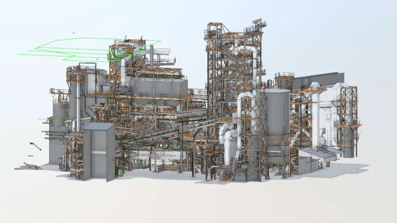
An overhead transmission upgrade must connect decisions made at individual towers with the behavior and constraints of an entire route. A new crossarm, foundation modification or relocated support can affect adjacent spans, access arrangements and the surrounding corridor. These relationships are difficult to communicate through disconnected drawings and uncoordinated three-dimensional files.
ScanM2 provides BIM modeling services for electric power transmission, developing organized digital models for transmission structures and their relevant site context. Models can combine verified existing-condition information with clearly identified proposed works, helping engineering teams review interfaces, coordinate disciplines and prepare project documentation.
Contact Us Now for a Free Consultation!
The model is an engineering information environment, not an automated structural or electrical design approval. Load cases, conductor mechanics, clearances and foundation adequacy must be established by the responsible specialists using appropriate calculations and verified inputs.
The Route Is the System, but the Tower Is the Work Package
For a long transmission corridor, a single highly detailed model is rarely the most useful delivery unit. Individual towers and work sites need identifiable model packages, while their locations and interfaces remain connected to route-level information. This allows design teams to focus on the assets affected by an intervention without losing the context of neighboring spans.
An agreed naming system can connect tower identifiers, route sections, structure types and design status. Model organization should support the owner’s asset records and engineering workflow rather than introduce arbitrary classifications that are difficult to maintain.
Separate Existing Conditions from Proposed Engineering
A useful transmission model distinguishes the installed configuration, proposed modifications and elements whose geometry is uncertain. Existing steelwork may be represented using measured surveys and reliable drawings. Proposed reinforcement, replacement members or new supports are modeled from approved design information, with their status made explicit.
Existing tower geometry
Visible members, crossarms and accessible interfaces can be modeled at the detail needed for the project. When measured data is required, Scan to BIM Services for Electric Power Transmission provides a route for reconstructing existing assets from suitable survey information.
Proposed changes
Design teams may need to compare a new member arrangement with existing bracing, examine a replacement crossarm envelope or study the position of a new support relative to surrounding infrastructure. The BIM model helps expose geometric conflicts, but does not establish whether a connection can carry the specified loads.
Unresolved conditions
Buried foundations, inaccessible connection details and undocumented modifications should not be presented as precisely verified. Assumptions and unresolved interfaces need to be recorded so they can be investigated before detailed design or construction.
What Belongs in a Transmission BIM Model?
The appropriate content depends on the project stage. A corridor-wide coordination model may be deliberately lightweight; a tower strengthening project may require more detailed structural objects at selected locations.
- Support structures: tower or monopole geometry, structural zones, crossarms and identifiable support assemblies.
- Foundations and interfaces: known foundation outlines, visible pedestals and verified attachment geometry.
- Route context: terrain references, access routes, adjacent assets and relevant crossing infrastructure.
- Conductors and insulator zones: appropriate schematic or measured representations, explicitly distinguished from calculated operating envelopes.
- Proposed construction: new supports, reinforcement elements, equipment arrangements and temporary spatial constraints where supplied by the design team.
- Asset information: identifiers, source references, revision status and agreed classification fields.
A high-detail representation of every tower component is not inherently more useful. Model detail should be assigned to interfaces where decisions depend on geometry, and the information requirements should be agreed before production.
Conductor Representation Is Not Conductor Design
An overhead conductor is not a rigid element fixed between two points. Its geometry changes with temperature, mechanical tension, wind and other operating conditions. A line model can include a reference alignment or an observed shape where survey data supports it, but neither is automatically a validated worst-case sag profile.
For clearance studies, engineers may bring separately calculated conductor positions and envelopes into the coordinated environment. The model can then help visualize relationships with terrain, roads, buildings or planned works. The underlying calculations, electrical requirements and compliance assessment remain the responsibility of qualified transmission-line engineers.
Coordination at Crossings and Constrained Sites
A tower replacement near a road, railway or industrial site creates interfaces beyond the support itself. The design may need to account for the footprint of new foundations, nearby structures, access limitations and construction staging. BIM can bring these spatial constraints into one review environment.
Survey-derived terrain and nearby assets may be linked rather than rebuilt as complex parametric objects. Where corridor geometry is missing, 3D Laser Scanning Services for Electric Power Transmission can support targeted capture of the existing site.
The presence of an object in a coordination model does not mean it has been checked against every statutory clearance, underground utility or construction safety requirement. The model should identify the scope and reliability of each input.
A Practical Model Federation Strategy
1. Establish a route reference
Confirm the project coordinate system, relevant tower positions, survey references and how local design origins relate to the route. Coordinate assumptions are particularly risky when work packages are prepared by different teams.
2. Define model boundaries
Decide which towers, spans, foundations and corridor features are needed for the current design decision. Keep adjacent context available without forcing every discipline into one large file.
3. Assign source and status
Record whether an object is surveyed, document-derived, proposed or provisional. Source traceability helps reviewers distinguish measured conditions from design intent.
4. Review critical interfaces
Check relevant spatial relationships and perform agreed model coordination. Clash detection can flag apparent geometric intersections, but its results must be assessed by engineers and should not be confused with a full technical compliance review.
5. Issue controlled deliverables
Deliver models with agreed naming, revision information, coordinate notes and any unresolved assumptions. This is particularly important when a project is divided into tower-by-tower construction packages.
Structural Steel, Foundations and Constructability
For lattice towers, BIM can support coordination between proposed steelwork and the known existing arrangement. It can help visualize member positions, check geometric access to selected connection regions and identify places where further site measurement is required.
Foundation modeling requires similar discipline. A visible pedestal does not reveal the size, depth or reinforcement of the buried foundation. Design information may be included when supported by records or investigation, but the model should not imply that underground details were verified by surface scanning.
Construction planning may use model views to discuss access routes, equipment positions and sequence interfaces. Such reviews complement, but do not replace, formal method statements, lifting plans or electrical safety procedures.

Interoperability and Information Handover
Depending on the client workflow, deliverables may include Revit models, IFC exchanges, coordinated references and model information schedules. Transmission-line engineering software may use specialized geometry and calculation formats, so interoperability requirements should be checked before modeling begins.
For project teams needing conventional documentation, As-Built Drawings Services for Electric Power Transmission can provide measured plans and elevations for existing assets. If source surveys require alignment or classification, Point Cloud Processing Services for Electric Power Transmission can prepare the underlying spatial data.
When Component Reconstruction Is Needed
Legacy structures may include nonstandard brackets, fittings or modified attachment details without reliable drawings. Where geometry is accessible and sufficiently measured, Reverse Engineering Services for Electric Power Transmission can support component-level geometric reconstruction. The resulting geometry still requires appropriate material verification, engineering checks and approval before any replacement or fabrication.
Plan the Model Around a Specific Upgrade Decision
Before starting, define the affected towers or route sections, the existing information available, the intended design and coordination tasks, the model detail required and the software environment. This helps keep the deliverable focused on practical engineering decisions instead of producing a visually elaborate but poorly documented model.
ScanM2 can support digital modeling for transmission infrastructure using project-specific source information and agreed modeling standards. Contact our team to discuss the intended use, model boundaries and delivery requirements.

