

As-Built Drawings for Electric Power Transmission
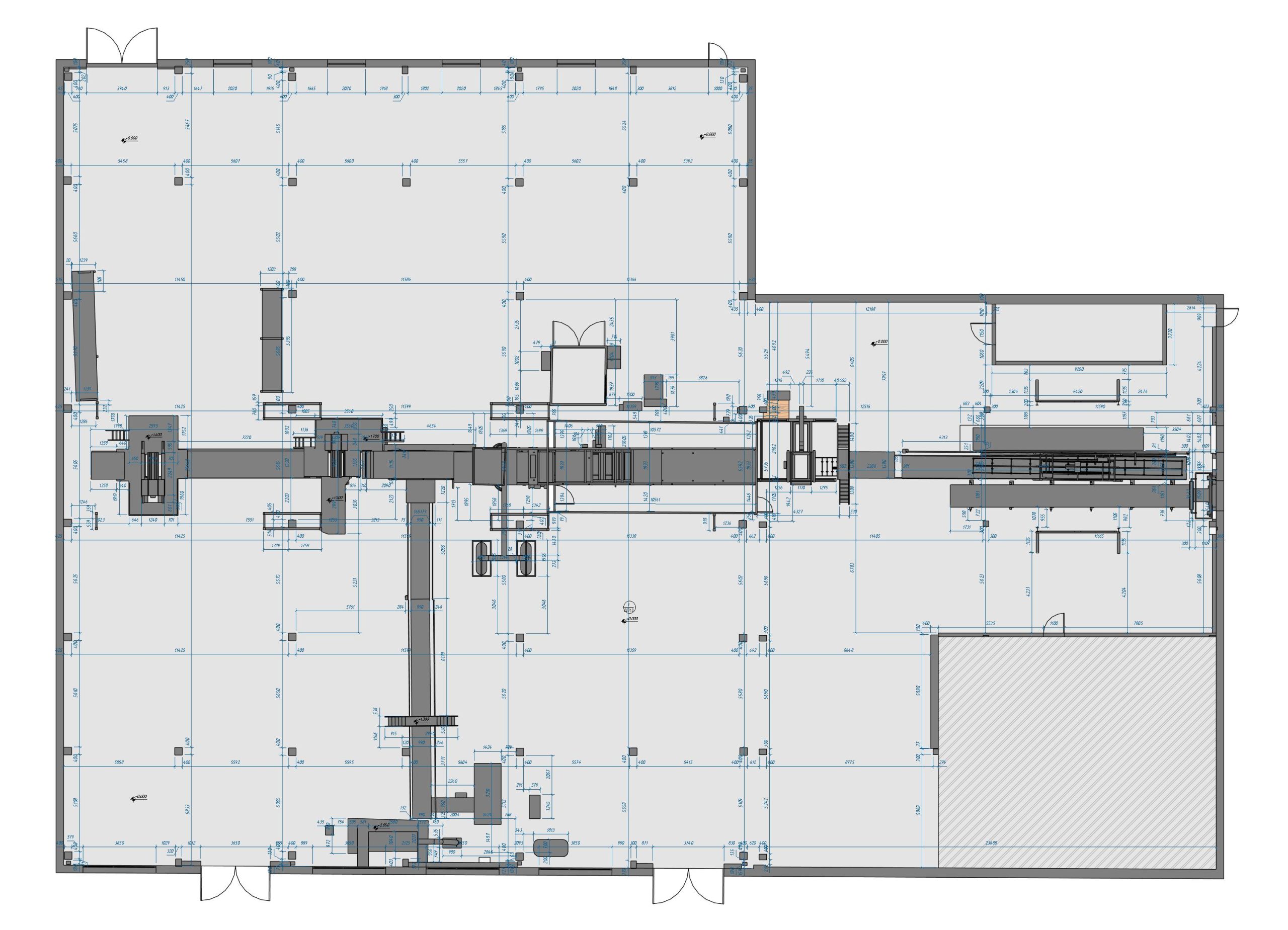
Transmission line drawings can remain in circulation long after a tower has been reinforced, a foundation repaired or the surrounding corridor altered. A design document may show what was intended to be built, while maintenance teams need to understand what can actually be verified on site.
ScanM2 provides as-built drawings services for electric power transmission, preparing measured plans, elevations, sections and selected details from suitable survey information and verified project records. The objective is to produce readable documentation that supports route upgrades, engineering reviews and asset management.
Contact Us Now for a Free Consultation!
Because an overhead line combines discrete structures with long spans, useful drawings must distinguish structural details from corridor-level relationships. They must also distinguish measured conditions from historic information or calculated design geometry.
The Drawing Set Depends on the Question Being Asked
There is no single as-built sheet that adequately describes an entire transmission route. A team preparing a tower reinforcement needs different drawings from a team reviewing a highway crossing or documenting the position of support structures across a route section.
The documentation package should therefore begin with a schedule of required views and their intended use. The available measurements, scale and verified references determine which dimensions can be responsibly shown.
Tower Documentation: Elevations Before Decorative Detail
For a lattice tower, orthographic elevations can communicate the arrangement of legs, bracing and crossarms more effectively than a perspective image. Drawings may include principal dimensions, visible member alignment and selected attachment zones where the survey resolution is adequate.
- General tower elevations: overall geometry and visible structural arrangement.
- Plan views at selected levels: relationships between tower legs, bracing zones and crossarms.
- Base and pedestal details: accessible foundation interfaces and surrounding levels.
- Selected connection areas: measured external geometry where sufficient survey coverage exists.
- Reference notes: tower identifier, coordinate basis, survey date and documented limitations.
A line in a drawing should not imply a degree of precision unsupported by the source. Hidden plates, bolts and internal details require additional measurements or reliable construction records.
Longitudinal Profiles for Route Understanding
A route profile can be valuable when a project involves multiple towers, changes in ground elevation or a major crossing. Such a drawing may show surveyed support locations, relevant terrain and selected observable line geometry along a defined alignment.
Conductor positions require careful labeling. A measured position at the survey date is not equivalent to a calculated maximum-sag profile. If a drawing includes engineering conductor curves, their source, assumptions and design conditions should be explicitly identified.
The line profile may also be supported by specialist transmission-line design tools. CAD drawings should preserve the distinction between a survey-derived record and a design calculation.
Crossings Need Their Own Sheets
Road and railway interfaces
Crossing documentation may need the position of support structures, surveyed ground levels and relevant physical features. Any statutory or operational clearance determination requires the appropriate engineering method and applicable authority requirements.
Waterways and uneven terrain
Valleys, riverbanks and steep slopes can complicate the interpretation of distances on a plan. Coordinated sections or profiles can show the terrain relationship more clearly, subject to survey coverage.
Industrial and urban constraints
Near buildings, pipelines or other assets, detailed plans can help locate existing obstacles and identify where additional investigation is necessary. Survey drawings do not automatically confirm property boundaries or underground utility positions.
From Survey Measurements to a Controlled Drawing
An as-built drafting workflow starts with a defined survey basis. Source data may include terrestrial scans, aerial LiDAR, control surveys and reliable project documentation. 3D Laser Scanning Services for Electric Power Transmission can provide detailed measurements of selected towers and accessible site features.
Where point clouds are used, their registration, alignment and coordinate system must be checked before drafting. Point Cloud Processing Services for Electric Power Transmission supports preparation of suitable survey data for the drawing workflow.
The drafting team then selects views and extracts dimensions consistent with the required scale and tolerance. Review should include comparison against source measurements, checks on annotations and confirmation that inferred geometry has not been presented as directly measured.

Measured, Record-Based and Unverified: Three Different Labels
Legacy power infrastructure may contain information gaps. A drawing can remain useful without disguising those gaps, provided it communicates the evidence behind the depicted elements.
Measured existing conditions
Dimensions and outlines derived from suitable field measurements can be identified as surveyed, with appropriate coordinate and date information.
Existing records
Historic drawings, owner asset registers or construction documents may provide member designations or concealed details. Their use should be documented, and they should not be silently treated as field-verified.
Unknown or inaccessible conditions
Buried foundations, obscured joints and inaccessible conductor attachment details may require additional inspection. Unresolved information should be flagged or omitted rather than reconstructed as fact.
A Drawing Register for Multi-Tower Projects
On a route with many structures, file naming and revision control can be as important as individual sheet quality. A useful register links each drawing to a tower or route section, its type, issue status and source information.
- Route or section reference: identifies the relevant part of the transmission system.
- Tower or crossing identifier: connects the sheet to an asset or location.
- Drawing type and scale: distinguishes general arrangement, elevation, profile and detail.
- Survey basis: records the coordinate reference and source date where relevant.
- Revision and limitations: shows what changed and which features remain unverified.
Consistent registers help engineers compare revisions without mistaking an earlier design sheet for an updated record of the installation.
How Drawings Support Retrofit and Maintenance
As-built tower elevations can support preliminary evaluation of reinforcement locations. A foundation interface plan may help an engineering team define further investigations. Corridor profiles can provide context for line relocation or crossing studies.
The drawings are reference documents, not evidence that every structural component is serviceable. Corrosion, hidden defects, material properties and load capacity require separate assessment. Similarly, a surveyed clearance shown on a sheet does not prove compliance under all operating conditions.
When a structured digital model is preferable to a collection of sheets, Scan to BIM Services for Electric Power Transmission can reconstruct suitable existing geometry as organized objects. BIM Modeling Services for Electric Power Transmission can support coordinated modeling of proposed changes.
When Standard Drawings Are Not Enough
A legacy bracket or nonstandard tower fitting may need component-level dimensional reconstruction rather than a general tower elevation. Reverse Engineering Services for Electric Power Transmission can help create measured geometric references for selected accessible components.
Such reconstruction is distinct from certifying a component for fabrication or service. Material selection, mechanical performance and approval remain engineering tasks.
File Formats and Handover
Depending on the agreed scope, deliverables may include DWG or DXF files, PDF drawing sets and associated survey references. The handover should identify units, drawing scales, coordinate conventions, survey sources and any exclusions.
For transmission projects, it is especially important to confirm whether the requested documents describe existing surveyed conditions, a design proposal or a post-construction record assembled from multiple sources. Those document types should not be conflated.
Commission Drawings That Answer Specific Engineering Questions
To define a drawing package, identify the relevant towers and route sections, the intended engineering use, required views, available records, survey coverage and preferred CAD standards. A clear scope makes it possible to prioritize meaningful dimensions and avoid unsupported detail.
ScanM2 prepares measured technical documentation for power infrastructure from suitable source information. Contact our team to discuss the required tower drawings, profiles, crossing sheets and delivery formats.

