

Factors Affecting Scan to BIM Accuracy (and How We QC Models)
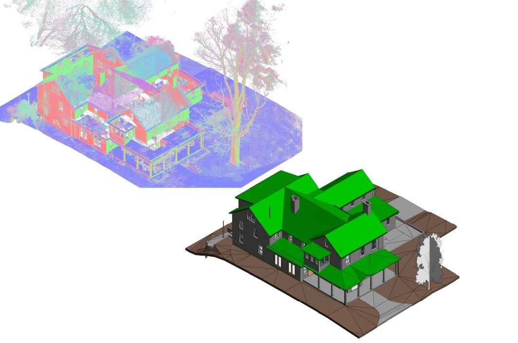

A laser scan and the BIM model built from it are not equally accurate, and they should not be judged by the same number. The scan records the building as millions of measured points. The model is an interpretation of those points: walls, floors, ducts and pipes drawn as clean Revit elements. Every step between the scanner and the final model can add a small difference, and the model’s purpose decides how much of that difference is acceptable.
This article follows that chain step by step: capture, registration, modeling and quality control. It explains which factors affect scan to BIM accuracy at each stage, which of them can be controlled, and how we check a model against the point cloud before delivery. If you are planning a project, our scan to BIM services page describes the full workflow.
Scan Accuracy vs Model Accuracy
It helps to separate two questions:
- How closely does the point cloud match the real building? This is measurement accuracy. It depends on the scanner, the site conditions and the registration.
- How closely does the model match the point cloud? This is modeling accuracy. It depends on modeling rules, the level of development, the modeler’s decisions and quality control.
The industry uses the same distinction. The USIBD Level of Accuracy (LOA) specification separates measured accuracy (reality to point cloud) from represented accuracy (point cloud to model) and gives a scale of levels that project teams can use when writing requirements. Whatever scale you use, the key point is that a model can never be more accurate than the scan it is built from, but it can easily be less accurate if the modeling and checking are weak.
Stage 1: The Scan
Our FARO laser scans have a typical accuracy of ±2–3 mm. That figure describes the captured points under normal conditions, not the finished model. The scanner itself is rarely the weak link; the conditions around it matter more. We cover the measurement side in detail in 3D laser scanning accuracy. Here is how field factors affect the data a modeler later works with.
| Factor | How it affects the data | How it is handled |
|---|---|---|
| Surfaces and reflections | Glass, mirrors, polished metal, glossy tiles and very dark materials return weak or false points; water surfaces can create ghost geometry | Extra scan positions at better angles, cleaning of false points, reference photos for problem areas |
| Site access | Locked rooms, occupied areas and blocked zones leave gaps that the modeler must fill by assumption | Access plan agreed before the visit; gaps marked so they are not modeled as measured |
| Scan density and coverage | Too few positions or too coarse a setting leaves thin edges, small pipes and connections poorly defined | Density matched to the smallest element that has to be modeled; overlap between positions |
| Control points and targets | Without control, long corridors, tall shafts and multi-level buildings can drift; the cloud cannot be tied to a project coordinate system | Targets or survey control where geometry is weak or coordinates are required |
| Temperature and movement | Heat, vibration, moving machinery, people and traffic add noise or doubled surfaces | Scanning at quieter times, repeat positions, removal of moving objects during processing |
| Hidden elements | The scanner records only visible surfaces: what is above closed ceilings, inside walls or under floors is not in the cloud | Ceilings opened where possible; hidden elements modeled from drawings only if agreed, and labeled as such |
Hidden elements deserve special attention. A point cloud is an honest record of what was visible on the day of scanning. If a duct runs above a closed ceiling, no amount of modeling care can make its position measured. A good scope says which areas are opened for scanning, and which elements, if any, may be modeled from existing drawings.
Stage 2: Registration
Each scanner position produces a separate scan. Registration joins them into one point cloud. If two scans are aligned with a small error, that error is built into everything modeled across the joint: a wall may appear slightly doubled, or a floor slab may not line up with the one above.
That is why registration is checked before modeling starts. We review the alignment statistics reported by the software, then look at the data itself: section cuts through walls and slabs, continuity of shafts and stairs between levels, and overlap areas where scans meet. Where control points or survey coordinates are part of the project, the cloud is checked against them. For a fuller explanation, see how point cloud registration works.
When a client sends us an existing point cloud, the same checks come first: registration quality, coverage of the areas to model and density for the required detail. We describe what makes data ready for modeling in what makes a point cloud BIM-ready.
Stage 3: Modeling
This is where most of the difference between scan accuracy and model accuracy appears, and most of it is a matter of decisions rather than errors.
Straight model or real conditions
Real buildings are not perfect. Walls lean or bow, floors sag, columns are slightly off the grid, ceilings vary in height. Revit elements, by default, are straight, plumb and level. So every as-built model needs a rule:
- Modeled as-is: elements follow the real geometry, including slopes, out-of-plumb walls and uneven slabs. This is closer to the point cloud and takes more effort.
- Modeled as design intent: elements are straightened and placed on a clean grid, as long as the deviation stays within an agreed modeling tolerance. This is easier to use for design but intentionally less faithful to the cloud.
Neither approach is wrong. The problem appears when nobody decides, and the client expects one while the modeler delivers the other. We agree on this rule, and on the modeling tolerance per element type, before modeling starts.
Level of development
Level of Development (LOD) sets how much geometry and information each element carries. A low LOD may show a wall as a simple box of the right thickness; a higher LOD includes openings, layers and more exact geometry. For MEP, a higher LOD means real sizes, fittings and connections. LOD and accuracy are related but not the same: a highly detailed element can still be placed in the wrong spot, and a simple one can be placed very precisely. For more on each level, see BIM LOD levels explained.
What is modeled and what stays in the cloud
Every element left out of the model is not an accuracy error, provided it was left out on purpose. Furniture, small fixtures and surface details often stay in the point cloud, which can be linked into Revit for reference. A written list of what to model avoids two opposite problems: important elements missing, or a model full of approximate objects that look measured but are not. We explain how to draw this line in Revit modeling from point cloud: what should be modeled and what shouldn’t.
Interpretation
Point clouds are not always clear. A pipe partly hidden behind a duct, a beam visible only from one side, insulation that hides the real pipe size: the modeler has to interpret. Clear modeling rules, reference photos and a habit of flagging uncertain elements instead of guessing all keep interpretation from becoming silent error.
Stage 4: How We QC Models
Quality control is a separate step, not something the modeler does “along the way”. Our process includes:
- Registration review before modeling, as described above.
- A sample check early in the project: one typical floor or zone is modeled and reviewed first, so any misunderstanding of the rules is caught before it repeats across the building.
- Model-to-cloud overlay. The point cloud is linked into the Revit model, and reviewers check elements in plans, sections and 3D views against the scan.
- Color deviation maps. The model surfaces are compared with the point cloud, and the differences are shown as a color map. Areas where the model departs from the cloud stand out immediately, and each one is either corrected or confirmed as an intentional simplification.
- Second-specialist review. A specialist who did not build the model checks it against the cloud, the scope and the modeling rules. A fresh pair of eyes finds things the author no longer sees.
- Completeness and standards check: every element in the agreed list is present, naming and parameters follow the template, and the .ifc export, if required, opens correctly.
Elements modeled from drawings, assumptions or partial data are marked, so the client knows which parts of the model are measured and which are not.
How to Get the Accuracy Your Project Needs
- Start from the purpose. Space planning, renovation design, MEP coordination and prefabrication need different levels of model accuracy.
- Define tolerance by element type. A single strict number for everything adds effort without adding value.
- Decide “as-is” or “design intent” before modeling starts.
- Plan access: open ceilings, unlock rooms and confirm restricted areas before the scanning visit.
- Ask for control points if the model must sit in a project or site coordinate system.
- Use a scale such as USIBD LOA if your organization already works with one, and state which areas it applies to.
- Agree on a review point after the first typical floor or zone.
Our Scan or Your Point Cloud
We travel to sites in any US state for FARO laser scanning, so the capture, registration and modeling stay in one workflow. If you already have a scan, we can also model from your data. In that case, the cloud is checked first, and any limits it places on model accuracy are discussed before modeling begins. Learn more about our point cloud to BIM services for existing buildings.
FAQ
What is the difference between scan accuracy and scan to BIM accuracy?
How accurate are your laser scans?
Why does the model not match the point cloud exactly?
How do you check a scan to BIM model for accuracy?
What is USIBD LOA?
Accuracy Is Built Step by Step
Scan to BIM accuracy is not a single property of a scanner. It is the result of good capture conditions, checked registration, clear modeling rules and independent quality control. When each step is planned and checked, the model can be trusted for the purpose it was built for. ScanM2 handles the whole chain, from FARO laser scanning in any US state or work from your point cloud to Revit models and .ifc delivery. Learn more about our scan to BIM services, or send us your project details to discuss the scope and the accuracy your model needs.

ScanM2 Launches ScanTrack: Manage Tasks Directly in a 3D Virtual Tour
18.10.2026
How integrating as-built documentation using advanced 3D scanning and laser scanning technology can revolutionize your real estate marketing strategy. Learn the benefits for agents and ...
Which 3D Laser Scanner Should Architects Choose, and When Is Outsourcing Better?
17.10.2026
How integrating as-built documentation using advanced 3D scanning and laser scanning technology can revolutionize your real estate marketing strategy. Learn the benefits for agents and ...

INTERGEO: How Laser Scanning Is Becoming a Foundation for Management and Decision-Making
24.09.2026
ScanM2 once again took part in INTERGEO, which was held in Munich this year. For us, the event is an opportunity to meet with partners, ...

How 3D Laser Scanning Measures Floor Flatness and Levelness
22.09.2026
Floor flatness and levelness can directly affect equipment installation, racking systems, automated material handling, production lines, flooring systems, and other construction activities that depend on ...

