
Reverse Engineering for Warehouses
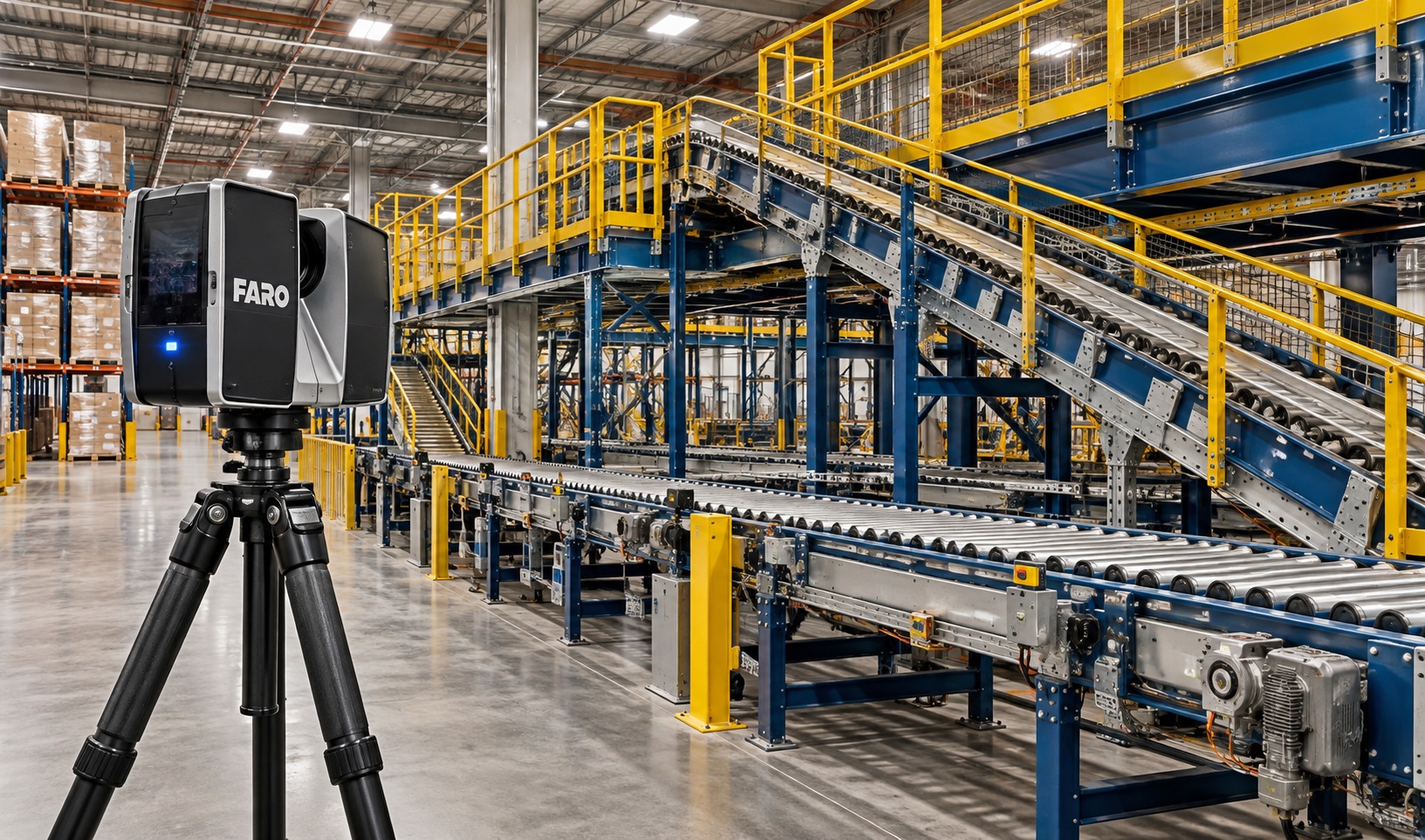
Warehouses contain more than walls, floors, and structural frames. Conveyors, platforms, equipment supports, access structures, guards, loading-area components, and custom-fabricated assemblies may all become part of a modernization project. When original drawings or reliable digital models are unavailable, these existing physical objects can become the starting point for new engineering documentation.
ScanM2 provides Reverse Engineering Services for Warehouses and distribution facilities. We capture existing geometry and convert measured conditions into digital information that can support equipment replacement, modification, integration, reconstruction, and facility upgrades.
Contact Us Now for a Free Consultation!
When the Existing Object Is the Only Reliable Reference
Warehouse equipment and supporting structures can remain in service long after their original documentation has become outdated or unavailable. Components may also have been modified during previous repairs, extensions, or operational changes.
In these situations, designing from an old drawing can introduce uncertainty. Reverse engineering begins with the geometry that physically exists at the facility and creates a digital reference for the next engineering task.
What Can Be Reverse Engineered in a Warehouse?
The scope is defined around the equipment or structure involved in the project rather than the entire warehouse building. Depending on the facility, relevant objects may include:
- Conveyor structures and supporting frames
- Equipment platforms and access structures
- Custom steel frames and supports
- Stairs, ladders, and guard structures
- Equipment bases and mounting interfaces
- Loading-area components
- Existing fabricated assemblies
- Other fixed objects requiring geometric documentation
Replacement Without Starting from Assumptions
Replacing an existing warehouse component is not always as simple as selecting a new object with similar overall dimensions. The replacement may need to fit existing supports, openings, adjacent equipment, access zones, or structural connections.
Measured geometry provides a reference for understanding these interfaces before a replacement solution is developed. This can be especially important when the surrounding warehouse cannot be substantially modified to accommodate new equipment.
Capturing the Interface, Not Just the Equipment
A reverse engineering project may require more than the geometry of a single object. The space around that object can determine whether a modification or replacement will work.
Depending on the task, the captured context can include nearby columns, floors, walls, beams, platforms, openings, adjacent equipment, and other physical constraints. This creates a spatial reference for evaluating how the existing object connects to the warehouse around it.
Reverse Engineering for Conveyor Modifications
Conveyor systems often pass through several parts of a warehouse and interact with supports, platforms, structural elements, and other equipment. When an existing conveyor route is modified, the available space and connection geometry can become as important as the conveyor itself.
Reality capture can document the relevant existing sections of the system together with surrounding conditions. The resulting data can then support the development of models or drawings for redesign and coordination.
Equipment Supports, Frames, and Mounting Conditions
Custom supports and frames are often specific to the equipment and building conditions for which they were originally created. If they need to be reproduced, modified, or incorporated into a new installation, basic manual dimensions may not provide enough information about their existing geometry.
Reverse engineering can capture the dimensions and spatial relationships required to create a digital representation of the relevant assembly and its connection points.
Working Around Existing Warehouse Operations
Removing equipment simply to measure it may be impractical when a warehouse remains operational. Reality-capture methods allow accessible visible geometry to be documented in its installed position.
Our 3D Laser Scanning Services for Warehouses can capture existing equipment together with surrounding building conditions without relying on a long sequence of isolated manual measurements.
From Captured Geometry to Engineering Data
The initial scan is not necessarily the final reverse engineering deliverable. The required output depends on what will happen after the existing object has been documented.
A project may require a processed point cloud for reference, a simplified 3D representation for coordination, a more detailed model of selected geometry, or drawings that communicate the dimensions and relationships required for subsequent engineering work.
When laser scanning is used, our Point Cloud Processing Services for Warehouses can prepare the captured dataset before subsequent modeling or documentation.
How Much of the Object Needs to Be Modeled?
Reverse engineering does not always require reproducing every small feature of an existing assembly. The required level of geometric detail should follow the purpose of the project.
A coordination model may primarily need the external geometry and connection interfaces. A project involving modification of an existing assembly may require more detailed representation of specific components. Defining these requirements before modeling helps avoid unnecessary work while preserving the geometry that matters for the engineering task.
Where Reverse Engineering Fits into Warehouse Modernization
Warehouse modernization often combines work at several scales. The building may require updated documentation, while individual equipment or fabricated components require more focused geometric reconstruction.
For building-level coordination, BIM Modeling Services for Warehouses can represent the required existing facility conditions. Reverse engineering can then focus more closely on selected equipment, structures, assemblies, or interfaces where additional geometric information is needed.
A Typical Reverse Engineering Workflow
- Define the object and engineering objective. Identify what needs to be replaced, modified, documented, or integrated.
- Determine the required surrounding context. Establish which nearby building or equipment geometry affects the task.
- Capture existing geometry. Record accessible physical conditions using the measurement method appropriate to the project.
- Process the measured data. Register, clean, and prepare captured information for subsequent work.
- Reconstruct required geometry. Create the model or documentation according to the defined engineering purpose.
- Prepare project deliverables. Supply the agreed digital files for the next design, coordination, or fabrication stage.
Common Uses of Warehouse Reverse Engineering
- Replacement of existing equipment
- Modification of conveyor systems
- Equipment integration
- Reconstruction of undocumented components
- Modification of platforms and supports
- Warehouse automation upgrades
- Documentation of custom fabricated structures
- Coordination with existing building geometry
Reverse Engineering Deliverables
Deliverables are selected according to the engineering objective and required downstream workflow. Depending on project scope, they may include:
- Registered point cloud data
- 3D geometry of selected existing objects
- Models of equipment interfaces and surrounding conditions
- 2D drawings where required
- Project-specific CAD or 3D files
- Supporting existing-condition documentation
Start with the Existing Geometry
When reliable drawings are missing, the installed object itself becomes the most direct source of geometric information. Capturing that geometry creates a measurable digital reference for understanding how existing warehouse equipment and structures can be replaced, modified, or incorporated into a new solution.
ScanM2 combines reality capture, point cloud processing, and 3D modeling to document the existing conditions required for warehouse reverse engineering projects.

