

As-Built Drawings for Condensation Electric Power Plant
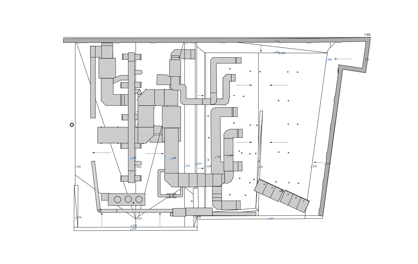
Technical documentation for a condensing power plant must reflect the equipment and structures that actually exist, not only the configuration shown in original construction drawings. Turbine replacements, condenser modifications, piping upgrades, and structural alterations can gradually create significant differences between archived documentation and current plant conditions.
ScanM2 provides As-Built Drawings Services for Condensing Power Plants, preparing measured plans, sections, elevations, equipment layouts, and technical drawings of existing power generation facilities. Our documentation supports reconstruction design, equipment replacement, engineering assessments, and the modernization of operating power plants.
Contact Us Now for a Free Consultation!
What Should As-Built Documentation Show at a Condensing Power Plant?
A condensing power plant includes multiple interconnected systems: steam turbines, generators, condensers, boilers, feedwater installations, cooling circuits, and auxiliary equipment. Each occupies a specific position within the building and connects to surrounding structures and engineering networks.
As-built drawings document the measurable existing arrangement of these facilities. Depending on the project, they may describe building geometry, equipment positions, pipe routes, structural interfaces, and the relationships between different technical levels.
The required drawing package is determined by the planned engineering work. A turbine modernization project needs different information from a condenser replacement or a steam pipeline reconstruction.
Types of As-Built Drawings for Power Generation Facilities
We prepare documentation according to the relevant building areas, engineering systems, required scale, and available measurement information.
| Drawing type | Documented information | Typical application |
|---|---|---|
| Floor plans | Walls, columns, openings, equipment positions, and accessible building geometry | Reconstruction planning and layout development |
| Building sections | Floor elevations, structural members, equipment heights, and vertical relationships | Equipment installation and structural coordination |
| Equipment layouts | Positions and dimensions of selected turbines, condensers, pumps, and auxiliary machinery | Equipment replacement and modernization |
| Piping arrangement drawings | Measured routes and positions of accessible piping and relevant connections | Pipeline modifications and interface planning |
| Structural drawings | Visible steel framing, platforms, supports, and relevant concrete elements | Structural modifications and engineering assessments |
| Elevations and technical views | Selected vertical surfaces, equipment arrangements, and structural geometry | Detailed design and technical documentation |
Drawing content and precision are agreed before production. Concealed elements or equipment characteristics that cannot be measured require separate verification.
Turbine Hall Plans and Sections
The turbine hall is one of the most important areas of a condensing power plant. It accommodates large generating equipment, structural systems, access platforms, overhead lifting installations, and connections to the condenser and steam piping networks.
Accurate plans and sections can document the geometry of the hall and the positions of major equipment relative to floors, columns, beams, and access openings.
For turbine-generator modernization, this information helps designers evaluate available installation space and identify the building elements that may affect proposed modifications.
Equipment Foundation Layouts
Measured drawings can show accessible foundation outlines, surrounding floor geometry, openings, and relevant dimensional relationships.
They provide geometric references for equipment coordination but do not establish foundation strength, concealed reinforcement, or vibration performance.
Vertical Sections Through Equipment Areas
Sections are especially useful where equipment occupies several elevations or interacts with overhead structures. They can show the relative heights of machinery, platforms, beams, and accessible technical installations.
Documenting Condenser Installations and Their Surroundings
Condensers are essential components of the steam cycle and may be installed in restricted technical spaces beneath or adjacent to turbine equipment.
As-built drawings can record the accessible external geometry of condenser housings, nearby supports, pipe connections, surrounding structures, and maintenance areas.
This documentation helps engineering teams assess the physical conditions affecting condenser replacement, reconstruction, or connection modifications.
Internal condenser components and operating characteristics must be documented using appropriate equipment records or separate technical inspections.
Steam and Feedwater Piping Drawings
Steam and feedwater systems connect major equipment across different plant areas. Their routes may include numerous bends, branches, valves, supports, and transitions between building levels.
For reconstruction projects, measured piping arrangement drawings can establish the visible position of existing lines and their relationship with nearby equipment and structures.
These drawings are particularly useful when developing new connections or assessing the space available for rerouting installations.
It is important to distinguish geometric piping documentation from process and instrumentation diagrams. As-built arrangement drawings show measured physical positions; they do not automatically verify process functionality, pipe specifications, or operating parameters.
When Original Power Plant Drawings Are No Longer Reliable
Many condensing power plants have undergone multiple modifications during their operational history. Equipment may have been replaced, pipelines relocated, openings created, and structural elements altered.
When these changes are not reflected in archived documentation, engineers risk developing new designs around incorrect assumptions.
Measured as-built drawings help establish a current geometric reference. They can also be compared with existing plans to identify relevant differences in the documented areas.
From 3D Measurements to 2D Technical Drawings
As-built drawings can be developed from several sources, including field measurements, existing verified survey data, and registered 3D point clouds.
For complex turbine halls, boiler buildings, and dense piping areas, laser scanning provides a practical method of collecting extensive geometric information.
The measured data is interpreted and converted into the required plans, sections, elevations, and equipment arrangements. Drawing elements are selected according to the intended engineering use rather than attempting to reproduce every visible detail.
When new survey measurements are required, our 3D Laser Scanning Services for Condensing Power Plants can provide the source geometry.
What Information Must Be Verified Before Drawing Production?
Reliable as-built documentation depends on clear requirements and suitable source information. Before production, the project team should define the following:
- Drawing purpose: reconstruction, equipment replacement, technical assessment, or general facility documentation
- Required areas: buildings, floors, equipment zones, and relevant interfaces
- Drawing types: plans, sections, elevations, layouts, or selected technical details
- Measurement requirements: agreed dimensional accuracy and critical features
- Reference system: coordinates, elevations, and applicable survey control
- Source limitations: concealed components, restricted access, and unavailable technical information
- Deliverable formats: required CAD files, PDF sheets, and documentation conventions
As-Built Drawings for Boiler House Reconstruction
Boiler houses contain large equipment assemblies, multi-level steel structures, service platforms, steam lines, and auxiliary systems. Their technical documentation must account for complex vertical and horizontal relationships.
Measured floor plans, sections, and equipment layouts can help engineers understand the existing arrangement before planning boiler component replacement, piping modifications, or structural alterations.
Where detailed spatial coordination is required, conventional drawings can be supplemented with a three-dimensional model.
As-Built Drawings or BIM Modeling: Which Is More Appropriate?
Not every reconstruction project requires a complete BIM model. Conventional as-built drawings may be sufficient when the design team needs measured dimensions, building plans, sections, and equipment layouts in a familiar CAD format.
BIM modeling becomes more relevant when several disciplines must coordinate complex three-dimensional installations or when a structured digital representation is required for ongoing engineering work.
For projects requiring coordinated models of existing equipment, piping, and structures, see our BIM Modeling Services for Condensing Power Plants.
Preparing Drawings for Phased Modernization Projects
Condensing power plants are often reconstructed in stages. One project may focus on a turbine unit, while another addresses the condenser, boiler equipment, or auxiliary systems.
As-built documentation can be organized into separate drawing packages for individual buildings, generating units, or technical areas.
Using consistent coordinates, elevations, and drawing conventions helps engineering teams combine information across successive modernization stages.
Our As-Built Documentation Workflow
The production process is adapted to the available measurements and the engineering purpose of the drawings.
- Define the documentation scope. Identify required drawings, facility areas, engineering applications, and dimensional requirements.
- Review source information. Examine existing plans, survey data, point clouds, and available technical documentation.
- Verify measurement coverage. Identify missing geometry and determine whether additional field measurements are necessary.
- Develop technical drawings. Prepare plans, sections, elevations, and equipment layouts using the verified geometric references.
- Check dimensional consistency. Review drawings against source measurements and agreed documentation requirements.
- Prepare the final package. Deliver the agreed CAD files, drawing sheets, and supporting information.
Typical Deliverables for Condensing Power Plants
The final documentation package depends on the project scope and may include:
- Measured floor plans of turbine halls and technical buildings
- Building and equipment sections
- Selected structural elevations
- Equipment arrangement and foundation layout drawings
- Measured piping arrangement drawings
- CAD documentation in agreed formats such as DWG or DXF
- PDF drawing sheets for technical review and coordination
Measurement Accuracy and Documentation Boundaries
The accuracy of as-built drawings depends on the measurement method, source data quality, geometric complexity, and required drawing detail.
For industrial facilities, inaccessible equipment surfaces, insulation, dense pipework, and restricted technical areas can limit measurement coverage.
Critical dimensions should be identified before data collection or drawing production. Where the required information cannot be established from available measurements, additional verification may be necessary.
Reliable As-Built Drawings for Power Plant Engineering
Accurate documentation of existing turbine halls, condenser installations, piping networks, and supporting structures provides a practical foundation for condensing power plant reconstruction.
ScanM2 prepares project-specific as-built drawings that help engineering teams work with verified geometric information when planning equipment replacement, structural modifications, and modernization projects.

