

Reverse Engineering for Condensation Electric Power Plant
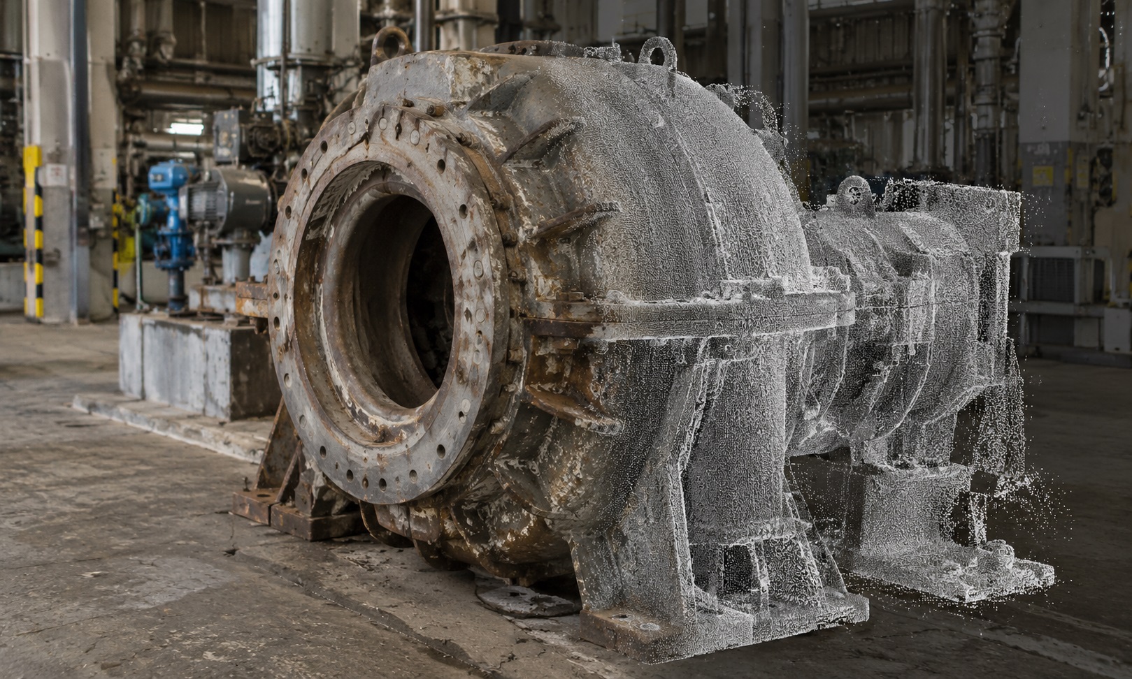
Condensing power plants often operate with equipment installed decades ago. Turbine assemblies, condenser components, pump housings, equipment supports, and mechanical connections may require replacement or modification even when original manufacturing drawings are incomplete, outdated, or unavailable.
ScanM2 provides Reverse Engineering Services for Condensing Power Plants, using measured geometry to reconstruct existing industrial components as digital CAD models and technical references. Our work supports equipment modernization, replacement-part development, dimensional verification, and engineering projects where reliable information about existing physical geometry is essential.
Contact Us Now for a Free Consultation!
When Existing Equipment Has No Reliable Drawings
Many power generation facilities have undergone repeated modifications during their operational life. Individual components may have been repaired, replaced, or adapted without corresponding updates to the original documentation.
This creates a practical problem when a component must be reproduced or integrated into a new system: the physical equipment becomes the most reliable available reference for its external geometry.
Reverse engineering helps convert those measurable physical features into structured engineering data. Instead of relying exclusively on historical drawings, engineers can work with models based on the current condition of accessible equipment.
Power Plant Components Suitable for Reverse Engineering
The scope of reverse engineering depends on the component’s accessibility, complexity, surface condition, and required accuracy. For condensing power plants, typical applications include mechanical assemblies, structural interfaces, and equipment-related components.
Turbine and Generator Equipment Interfaces
Modernization projects may require accurate external geometry of turbine casings, mounting arrangements, baseplates, supporting structures, and accessible connection interfaces.
Reconstructed CAD geometry can help engineers assess available space, compare existing and proposed equipment dimensions, and plan modifications to surrounding installations.
Condenser and Heat Exchange Components
Condenser reconstruction projects may involve external housings, nozzle locations, flanges, pipe connection geometry, support elements, and other accessible components.
Measured geometry can be used to prepare replacement designs or evaluate how new equipment will interface with existing piping and structural systems. Internal features that cannot be measured directly require additional information or inspection.
Pump Housings, Supports, and Mechanical Parts
Pump housings, mounting brackets, adapters, equipment supports, and other mechanical components can be reconstructed when their physical geometry is accessible and suitable measurement methods are available.
Depending on the task, the resulting CAD model may represent the measured existing condition or a proposed replacement geometry developed using additional engineering requirements.
Reverse Engineering Is More Than Converting a Scan into a Model
A 3D scan captures measurable surfaces, but a reverse-engineered CAD model must organize that information into usable geometric features.
For example, a scanned equipment housing may contain surface irregularities, manufacturing tolerances, corrosion, or deformation. Simply tracing every measured deviation does not necessarily produce a useful engineering model.
The modeling approach must reflect the purpose of the project: documenting the current condition, approximating nominal geometry, preparing a replacement component, or verifying a mechanical interface.
| Digital representation | What it contains | Typical use |
|---|---|---|
| Point cloud | Measured 3D coordinates of visible surfaces | Reference measurements and geometric inspection |
| Polygon mesh | Surface representation constructed from measurement data | Shape review and geometric reconstruction |
| Surface CAD model | Reconstructed surface geometry | Complex external shapes and design references |
| Solid CAD model | Structured three-dimensional solid geometry | Mechanical design, modifications, and integration |
| Parametric CAD model | Features and dimensions that can be edited where modeled parametrically | Design changes and component development |
Reconstructing Mechanical Geometry from Physical Measurements
The reconstruction method is selected according to component geometry and the engineering objective. Large equipment housings and support structures may be measured using terrestrial laser scanning, while smaller parts or fine mechanical details may require higher-resolution scanning or complementary dimensional measurement.
After data acquisition, the geometry is evaluated to identify relevant surfaces, axes, connection points, and dimensional relationships.
For mechanical components, particular attention may be given to:
- Mounting-hole positions and accessible bolt patterns
- Flange geometry and pipe connection interfaces
- Equipment envelopes and clearance boundaries
- Accessible cylindrical and planar surfaces
- Support locations and structural contact surfaces
- Relative positions of connected mechanical assemblies
Critical fits, hidden dimensions, material properties, and manufacturing tolerances cannot be established from external scanning alone. These requirements must be supported by appropriate additional measurements, technical documentation, or engineering analysis.
Existing Geometry Versus Nominal Design Geometry
One of the most important decisions in reverse engineering is whether the digital model should reproduce the existing physical condition or represent an intended nominal design.
An older component may have worn surfaces, deformation, previous repair modifications, or deviations from its original manufactured dimensions.
A model intended for condition assessment may need to preserve those deviations. A model intended for manufacturing a replacement component may instead require an engineered interpretation of the original functional geometry.
These are different deliverables and should not be treated as interchangeable.
Dimensional Verification of Reconstructed Components
After CAD reconstruction, the model can be compared against the available measurement data to evaluate geometric agreement.
Depending on the project, verification may involve surface deviation analysis, cross-sectional comparisons, selected dimensional checks, or inspection of critical connection features.
Deviation Analysis
A deviation comparison can identify differences between a reconstructed CAD surface and measured points. Such analysis helps reveal modeling inconsistencies or departures from the physical geometry.
However, the deviation result must be interpreted in relation to measurement uncertainty, surface condition, alignment quality, and the intended function of the component.
Checking Critical Interfaces
Where a replacement component must connect to existing equipment, interface dimensions may require additional verification beyond the general surface comparison.
For example, a flange or mounting assembly may require direct measurement of hole locations, mating surfaces, and functional clearances. The necessary verification method should be established before reconstruction begins.
Reverse Engineering for Power Plant Modernization
Reverse engineering is particularly valuable when existing equipment must remain connected to new machinery, piping, or supporting structures.
During turbine or condenser modernization, engineers may need to design adapters, revised supports, replacement housings, or modified connection arrangements around equipment that cannot be fully documented from historical drawings.
A reconstructed model provides a geometric reference for evaluating these modifications before fabrication or installation.
For wider facility coordination, reverse-engineered mechanical components can be integrated with BIM Modeling Services for Condensing Power Plants, allowing equipment geometry to be reviewed alongside building structures and engineering systems.
What If the Equipment Cannot Be Removed?
Power plant equipment is often too large, heavy, or operationally important to be dismantled solely for measurement.
In such cases, reverse engineering can focus on accessible external surfaces and interfaces while the equipment remains installed, subject to site safety requirements and operating restrictions.
Measurements may be planned around scheduled outages, maintenance windows, or approved access periods. Areas concealed by insulation, protective covers, or adjacent machinery must be identified as limitations unless additional access is provided.
Where the task also requires documenting surrounding plant geometry, 3D Laser Scanning Services for Condensing Power Plants can support broader spatial measurement of the installation environment.
Our Reverse Engineering Process
The workflow is defined around the intended engineering output rather than a fixed scanning or modeling procedure.
- Define the component and objective. Establish whether the model is required for documentation, replacement, modification, or dimensional verification.
- Review available technical information. Examine existing drawings, photographs, specifications, and access conditions.
- Plan and perform measurements. Select suitable scanning and dimensional measurement methods for the required features.
- Prepare measurement data. Register, clean, and organize the acquired geometry as necessary.
- Reconstruct CAD geometry. Create the agreed surface, solid, or parametric representation.
- Verify the model. Compare relevant reconstructed features with source measurements and identify limitations.
- Deliver engineering files. Export the agreed model formats and supporting documentation.
CAD Deliverables and Engineering Documentation
Reverse engineering deliverables depend on the intended use, source data, and agreed modeling scope.
| Deliverable | Application |
|---|---|
| STEP CAD model | Exchange of reconstructed solid or surface geometry between compatible CAD systems |
| IGES surface model | Transfer of supported surface geometry |
| Native CAD project | Further editing in the agreed modeling software |
| Reference mesh or point cloud | Review of measured source geometry |
| Dimensional drawings | Documentation of selected measurable features and interfaces |
| Deviation comparison | Assessment of agreement between reconstructed geometry and measurement data |
Not every project requires all of these outputs. Manufacturing-ready drawings, material specifications, tolerance definitions, and engineering approval must be explicitly included in the scope if required.
How Reverse Engineering Differs from As-Built Documentation
Both services rely on information about existing physical conditions, but they address different engineering needs.
As-Built Drawings for Condensing Power Plants generally document the arrangement, dimensions, and location of buildings, structures, equipment, and engineering systems.
Reverse engineering focuses more directly on reconstructing component geometry for mechanical design, modification, replacement, or verification.
For example, an as-built drawing may show the location and overall dimensions of a pump installation. A reverse-engineered CAD model may describe the accessible geometry of a specific pump housing or mounting component in greater detail.
Planning a Reverse Engineering Project at an Operating Power Plant
Before measurements begin, it is important to identify the required component, its operating environment, the purpose of reconstruction, and the features that must be represented accurately.
For large equipment, measurement access and site restrictions can significantly influence the available data. For precision mechanical parts, the choice of measurement method and required dimensional tolerances may be more important than the overall size of the component.
ScanM2 helps industrial clients develop measured digital geometry for existing equipment, supporting engineering decisions where conventional documentation is insufficient. Contact our team to discuss the component, available source information, and required CAD deliverables.

