

As-Built Drawings for Nuclear power plant
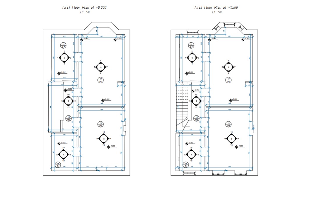
Engineering modifications at a nuclear power plant depend on accurate information about the existing facility. Before replacing equipment, modifying technical rooms, or planning new service routes, project teams need to understand the actual dimensions, elevations, structural arrangements, and equipment positions within the affected areas.
ScanM2 provides As-Built Drawings Services for Nuclear Power Plants, preparing measured plans, sections, elevations, and technical layouts from suitable survey data and verified project information. Our documentation services help engineering teams establish a geometric reference for modernization, reconstruction, and maintenance planning within authorized facility areas.
Contact Us Now for a Free Consultation!
What Should an As-Built Drawing Tell an Engineer?
An as-built drawing should communicate the relevant physical arrangement of an existing facility in a format that engineers can interpret, measure, and use for subsequent work. It is not simply a reproduction of the original construction documentation.
For a nuclear power plant modernization project, the required information may include structural dimensions, floor elevations, equipment locations, openings, accessible piping routes, and the relationship between different technical levels.
The content depends on the engineering task. A drawing prepared for equipment replacement may emphasize foundations and connection locations, while documentation for building refurbishment may focus on walls, floors, structural elements, and openings.
As-built documentation should also identify relevant measurement limitations. A drawing cannot establish the geometry of concealed or inaccessible elements unless suitable supporting information is available.
Technical Drawings for Different Nuclear Facility Areas
Nuclear power plants contain multiple building types and technical environments. Their documentation requirements vary according to installed equipment, structural complexity, and the intended modernization activities.
| Facility area | Potential drawing types | Documentation purpose |
|---|---|---|
| Turbine and generator halls | Floor plans, equipment layouts, longitudinal and transverse sections | Document machinery positions, structural geometry and available space |
| Auxiliary technical buildings | Room plans, elevations, technical sections | Support building modifications and equipment replacement |
| Pump and heat exchanger rooms | Equipment arrangement drawings, sections, connection layouts | Record accessible equipment positions and interfaces |
| Piping galleries | Pipe arrangement plans, selected sections and elevations | Document visible routing and spatial relationships |
| Ventilation areas | Duct layouts, equipment plans, sections | Support technical system modifications |
| Industrial support structures | Structural plans, elevations, selected connection details | Provide geometric references for reconstruction planning |
All documentation activities within nuclear facilities depend on the approved project scope, applicable safety procedures, and facility operator authorization.
Equipment Layouts: Documenting the Existing Installation
Equipment replacement projects often require a clear understanding of the existing installation rather than a general building plan.
Equipment layout drawings can document the position of machinery relative to structural grids, floors, walls, foundations, and adjacent installations. Depending on the available measurements, they may also show accessible connection locations, maintenance platforms, and selected dimensional relationships.
For example, modernization of an auxiliary pump installation may require information about the equipment footprint, baseplate location, nearby piping, and available access space.
These drawings provide geometric information for engineering review. They do not independently establish mechanical performance, foundation capacity, or the suitability of replacement equipment.
Sections and Elevations Reveal What Floor Plans Cannot
Complex industrial installations often extend across several levels. A floor plan may show the horizontal arrangement of equipment but cannot fully describe vertical clearances, overhead piping, platforms, or structural relationships.
Sections and elevations provide additional views of the existing geometry. They can be especially useful in turbine buildings, multi-level technical rooms, and piping galleries where equipment occupies different elevations.
Depending on the scope, technical sections may document:
- Floor-to-floor heights and relevant elevation references
- Positions of beams, columns, and accessible structural elements
- Equipment heights and installation envelopes
- Overhead piping and ductwork arrangements
- Service platforms, stairs, and accessible support structures
- Relevant openings and vertical clearance constraints
The drawing scale and level of detail should be selected according to the dimensions and engineering decisions that the documentation must support.
Piping and Technical Systems: What Can Be Documented Reliably?
Nuclear power plant facilities contain extensive technical networks, including piping, ventilation systems, cable infrastructure, and mechanical installations. Their physical arrangement can be complex, particularly in older facilities that have undergone multiple modifications.
Measured drawings can represent visible routes, external dimensions, supports, and relevant connections where sufficient survey information is available.
However, the geometric appearance of a pipe does not establish its function, operating pressure, material specification, wall thickness, or safety classification. These properties require verified technical records and appropriate engineering review.
Insulated pipes and concealed connections present additional limitations. If their actual geometry cannot be measured, the drawing should distinguish verified visible features from information obtained through other sources.
The Difference Between Measured, Documented, and Assumed Geometry
One of the most important aspects of preparing existing-condition drawings is identifying the origin of the represented information.
Historical drawings may describe the intended original installation, while current measurements reflect the accessible physical condition at the time of the survey. These sources may not always agree.
Measured Geometry
Geometry established from suitable survey measurements can be used to document the accessible physical condition of selected elements. Its reliability depends on measurement quality, visibility, and the agreed accuracy requirements.
Geometry Derived from Existing Documentation
Original drawings, technical records, and historical models may provide information about features that are difficult to measure. Such information should be identified appropriately when it has not been verified against current physical conditions.
Unverified or Simplified Geometry
Where measurements and reliable documentation are unavailable, the project may require an intentionally incomplete or simplified representation. Any assumptions must be clearly identified and should not be presented as verified existing conditions.
This distinction helps prevent errors when technical drawings are used for equipment replacement or reconstruction planning.
Using 3D Laser Scanning to Prepare As-Built Drawings
Traditional measurements may be sufficient for relatively simple spaces. However, complex industrial rooms and multi-level equipment installations can benefit from a coordinated three-dimensional survey.
3D Laser Scanning Services for Nuclear Power Plants can provide high-density measurements of accessible surfaces within authorized survey areas.
After registration and quality review, the resulting point cloud can be used as a geometric reference for preparing plans, sections, elevations, and selected equipment layouts.
The drawing process involves interpreting the measurements, identifying relevant objects, selecting suitable views, and documenting the agreed dimensions.
A point cloud does not automatically produce a complete or verified technical drawing. Additional drafting, measurement interpretation, and quality control are required.
Dimensional Accuracy and Drawing Verification
The required accuracy depends on how the drawing will be used. General building documentation and critical equipment interface verification may require different measurement methods and tolerances.
For example, a room plan intended for preliminary layout development may not require the same dimensional precision as documentation of a machinery mounting interface.
Before work begins, the project team should identify critical dimensions, required measurement reliability, drawing scales, and any features requiring independent verification.
Quality control may include checking selected dimensions against the source measurements, reviewing coordinate references, confirming drawing completeness, and identifying unresolved geometry.
Where specialized dimensional accuracy is necessary, additional metrology or direct measurements may be required beyond conventional facility laser scanning.
Preparing Documentation for Phased Reconstruction
Modernization work may be completed over multiple maintenance periods or reconstruction stages. Equipment can be removed, replaced, or repositioned between survey campaigns.
As-built drawings should therefore be associated with the physical configuration and measurement date they represent.
When new measurements are collected after modifications, the documentation can be updated to reflect the verified changes within the agreed scope.
Careful revision management helps distinguish original conditions, proposed modifications, and completed installations.
When Drawings Are More Useful Than a Full BIM Model
Not every engineering task requires a complete three-dimensional information model.
For some projects, measured floor plans, equipment layouts, and selected technical sections provide the information needed for engineering review and documentation.
As-built drawings may be particularly appropriate when the deliverable must be reviewed in a conventional CAD environment, included in an existing technical drawing set, or focused on a limited installation area.
For projects requiring coordinated digital objects and multidisciplinary information management, BIM Modeling Services for Nuclear Power Plants may be more suitable.
The two approaches can also complement each other when the project requires both structured models and conventional technical drawings.
As-Built Drawing Deliverables
The final documentation package is determined by the authorized facility areas, intended engineering uses, and agreed drawing requirements.
| Deliverable | Typical content |
|---|---|
| Floor plans | Room layouts, structural grids, openings and selected equipment positions |
| Building sections | Floor elevations, structural geometry and vertical spatial relationships |
| Equipment layouts | Machinery footprints, accessible connection locations and surrounding installations |
| Piping arrangement drawings | Visible pipe routes, selected supports and relevant spatial relationships |
| Technical elevations | Selected equipment, building and structural arrangements |
| CAD files | Editable documentation in agreed compatible formats |
| PDF drawing sets | Review and distribution of approved drawing outputs |
Specialized engineering drawings, manufacturing details, system specifications, and regulatory approval documentation must be explicitly included in the scope if required.
Our Approach to Existing-Condition Documentation
We organize as-built documentation around the technical decisions that the drawings must support.
- Define the drawing scope. Identify required buildings, technical areas, equipment, views, scales, and critical dimensions.
- Review available source information. Assess existing drawings, measurement datasets, and approved technical references.
- Evaluate measurement coverage. Identify accessible geometry, missing information, and areas requiring additional authorized surveys.
- Prepare technical drawings. Develop plans, sections, elevations, and selected equipment layouts using suitable source information.
- Verify relevant dimensions. Review critical geometry and drawing consistency against the agreed requirements.
- Document limitations. Identify unverified features, source assumptions, and relevant measurement restrictions.
- Deliver approved files. Prepare the agreed CAD and PDF outputs under applicable information handling requirements.
Documentation Requirements at Nuclear Facilities
Nuclear power plant projects may involve additional restrictions related to facility access, technical information, data storage, and the distribution of drawings.
The scope of permitted measurements and documentation must be agreed with the facility operator and responsible project stakeholders.
Where specialized technical or safety-related information is required, it must be obtained from approved sources and reviewed by appropriately qualified personnel.
As-built documentation services do not replace nuclear safety assessments, structural verification, equipment qualification, or regulatory approval procedures.
Service availability for a particular facility depends on the applicable authorization, access conditions, personnel requirements, and approved project scope.
As-Built Drawings for Nuclear Power Plant Modernization
Reliable drawings of existing conditions help engineering teams understand the physical constraints of complex industrial facilities and prepare technical information for proposed modifications.
ScanM2 provides industrial measurement and as-built documentation services. Contact our team to discuss the required facility areas, available survey data, drawing formats, dimensional requirements, and applicable restrictions. We can assess the proposed documentation scope and suitable deliverables.

