

Reverse Engineering for Nuclear power plant
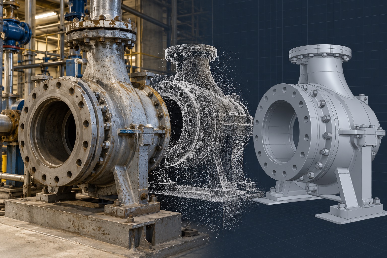
Nuclear power plants may contain equipment and mechanical installations that have remained in service through multiple modernization cycles. Over time, original manufacturing drawings, native CAD models, and detailed dimensional records can become difficult to obtain. When engineers need to assess an existing component, plan a replacement, or develop a modification, incomplete geometric documentation creates additional challenges.
ScanM2 provides Reverse Engineering Services for Nuclear Power Plants, using suitable 3D measurement data to reconstruct the geometry of existing industrial components, equipment assemblies, and mechanical interfaces. Our services support the preparation of digital geometric references for authorized engineering and modernization projects, subject to facility requirements and the agreed technical scope.
Contact Us Now for a Free Consultation!
When Original Equipment Geometry Is No Longer Available
Industrial equipment may undergo modifications throughout its service life. Components can be replaced, support arrangements altered, and mechanical connections adapted to new operating configurations.
As a result, the actual geometry of an installed component may differ from its original manufacturing documentation. In other cases, detailed drawings or editable CAD models may no longer be available to the engineering team.
Reverse engineering addresses the geometric information gap by measuring an existing physical object and reconstructing its relevant shape in a digital environment.
The resulting geometry can help engineers document existing equipment, study spatial interfaces, and develop preliminary concepts for authorized modifications. It does not independently establish the component’s material properties, manufacturing tolerances, mechanical performance, or suitability for continued service.
What Can Be Reconstructed from Physical Measurements?
The scope of reverse engineering depends on the physical object, measurement accessibility, required geometric detail, and intended engineering application.
For nuclear power plant projects, potential applications may involve accessible components in turbine-generator buildings, auxiliary equipment installations, and other authorized industrial areas.
| Component or installation | Potential reconstruction scope | Engineering application |
|---|---|---|
| Equipment housings | External geometry, mounting surfaces, accessible openings | Geometric documentation and equipment arrangement studies |
| Pump and motor assemblies | Equipment envelopes, accessible interfaces, mounting geometry | Replacement planning and spatial coordination |
| Mechanical supports | Brackets, frames, support structures and connection geometry | Modification planning and dimensional reference |
| Pipe fittings and connection assemblies | Accessible external surfaces and connection locations | Interface documentation and routing studies |
| Industrial machinery components | Selected surfaces, profiles and geometric features | CAD reconstruction and engineering evaluation |
| Equipment foundations and base structures | Accessible mounting geometry and spatial relationships | Installation planning and coordination |
Not every component can be reconstructed using the same measurement technology. Small precision parts, internal features, and tight-tolerance interfaces may require specialized metrology rather than conventional facility laser scanning.
Three Different Outputs from Reverse Engineering
Reverse engineering does not always mean producing a manufacturing-ready solid model. Different projects require different representations of the measured object.
1. Measured Surface Representation
A point cloud or polygon mesh can represent the visible surface geometry of a measured component. This output is useful for geometric inspection, visualization, and comparison with existing digital models.
Surface measurements may contain gaps where the object was inaccessible or hidden from the measuring instrument.
2. Reconstructed CAD Geometry
Measured surfaces can be interpreted and reconstructed as CAD geometry, including suitable solids, surfaces, and geometric features.
The reconstruction method depends on the object’s shape, available measurements, and required model accuracy. The resulting CAD model may contain simplified or interpreted features that must be identified where relevant.
3. Engineering Interface Model
Some projects require only the dimensions and spatial relationships that influence a proposed modification. In these cases, a model may focus on mounting interfaces, connection locations, equipment envelopes, or other selected features.
This targeted approach can reduce unnecessary modeling while providing the geometry needed for subsequent engineering work.
Reverse Engineering Is Not the Same as Scan to BIM
Both services can use measured three-dimensional data, but they address different engineering needs.
Scan to BIM Services for Nuclear Power Plants focus on reconstructing existing buildings, technical spaces, and selected engineering systems as structured information models.
Reverse engineering concentrates on the geometry of individual components, mechanical assemblies, and specific equipment interfaces.
For example, Scan to BIM may represent the position and approximate external geometry of a pump installation within a technical room. Reverse engineering may instead focus on the accessible mounting geometry or external features of a particular component.
The required accuracy, measurement equipment, and CAD reconstruction methods may therefore differ substantially.
Reconstructing Equipment Interfaces for Modernization
One practical application of reverse engineering is documenting the geometry of existing equipment interfaces before a proposed modification.
Suppose an engineering team needs to evaluate the replacement of an auxiliary mechanical unit. Existing drawings may describe the original installation, but the actual mounting arrangement may have been modified during previous maintenance work.
Measurements of accessible surfaces can help establish a geometric reference for the installed equipment and its surrounding interfaces.
Depending on the scope, the reconstructed information may include:
- Equipment mounting positions and accessible support geometry
- External component dimensions and spatial envelopes
- Accessible flange and connection locations
- Geometric relationships between adjacent components
- Selected reference planes, axes and alignment features
- Areas requiring further dimensional verification
These measurements can support engineering studies, but they do not determine whether a replacement component is mechanically, operationally, or safety-qualified for the intended installation.
Choosing the Appropriate Measurement Method
Measurement technology should be selected according to the component size, surface characteristics, accessibility, and required dimensional accuracy.
Terrestrial laser scanning is useful for capturing large equipment envelopes, surrounding installations, and structural relationships. More detailed component geometry may require close-range 3D scanning, portable metrology systems, or other specialized measurement methods.
Critical interfaces may also require direct dimensional measurements or independent verification.
The required tolerance must be defined before selecting the measurement approach. A visually detailed model is not necessarily accurate enough for manufacturing or precision assembly.
For larger installation environments, 3D Laser Scanning Services for Nuclear Power Plants can provide suitable spatial measurements within approved facility areas.
From Physical Component to CAD Model
The reverse engineering process involves several stages of geometric interpretation. The exact sequence depends on the source data and the intended output.
Measurement and Source Review
Available measurements, historical drawings, and technical references are reviewed to determine which geometric features can be reconstructed reliably.
Data Preparation
Suitable scan data is registered, cleaned, and organized for geometric reconstruction. Depending on the original measurements, this may include segmentation and preparation of relevant component surfaces.
These operations can be supported by Point Cloud Processing Services for Nuclear Power Plants.
Geometric Reconstruction
Relevant surfaces and features are reconstructed using suitable CAD methods. Depending on the component, this may involve analytical shapes, surface modeling, solid modeling, or simplified representations.
Verification Against Measurements
The reconstructed geometry can be compared with the source data to assess relevant deviations and identify areas requiring additional verification.
Engineering Data Delivery
Approved models and supporting information are prepared in the agreed formats for authorized engineering use.
Reconstruction of Worn or Modified Components
Existing industrial components may exhibit wear, deformation, corrosion, or modifications that affect their measured geometry.
Reverse engineering can document the current measurable shape of such a component, but it cannot automatically determine its original design geometry.
For example, a worn surface may differ from the intended manufacturing profile. Reconstructing that surface directly would reproduce the observed condition rather than establish the original nominal dimensions.
Recovering a nominal design may require verified manufacturing drawings, engineering calculations, material information, dimensional analysis, and approval by appropriately qualified specialists.
For nuclear-related equipment, this distinction is particularly important because reproducing a component’s shape does not establish its technical suitability or regulatory compliance.
Measured Geometry Does Not Reveal Material or Performance
Three-dimensional measurements primarily describe accessible geometry. They do not independently establish the physical and operational properties of the measured object.
A reconstructed CAD model cannot, by itself, confirm:
- Material composition and mechanical properties
- Internal defects or concealed damage
- Original manufacturing tolerances
- Pressure, temperature or fatigue performance
- Seismic or environmental qualification
- Safety classification or regulatory acceptability
- Fitness for service or remaining operating life
These matters require separate technical evidence, testing, analysis, and applicable approval procedures. Reverse engineering provides geometric information that may support such work within the authorized scope.
Comparing Reconstructed Geometry with Existing CAD Data
When historical CAD files or design drawings are available, measured geometry can be compared with the existing digital representation.
Such comparisons may help identify differences in external dimensions, equipment positions, or selected geometric features.
However, a detected deviation does not automatically indicate a defect. It may result from manufacturing tolerances, intentional modifications, measurement uncertainty, wear, or differences between nominal and installed conditions.
The significance of any deviation must be assessed by the responsible engineering specialists using appropriate technical criteria.
Reverse Engineering for Auxiliary and Non-Safety-Critical Installations
Potential reverse engineering applications may include selected auxiliary machinery, industrial supports, maintenance equipment, and other installations where geometric documentation is needed.
Even where a component is not classified as safety-related, its modification may affect adjacent equipment, building structures, maintenance access, or other facility systems.
The actual component classification and applicable requirements must be established by the facility operator or responsible engineering organization.
ScanM2 does not independently determine nuclear safety classifications through geometric measurement or CAD reconstruction.
CAD Deliverables and Geometric Documentation
The deliverables depend on the measured component, intended engineering use, required geometric accuracy, and available source information.
| Deliverable | Purpose |
|---|---|
| Reconstructed CAD model | Digital representation of agreed component geometry |
| Surface or mesh model | Representation of measured external surfaces |
| Equipment interface geometry | Reference for mounting and spatial coordination studies |
| Selected dimensional drawings | Documentation of agreed measurable features |
| Geometry comparison outputs | Review of differences between measurements and reference geometry |
| Model limitations and source information | Identification of measurement coverage, assumptions and reconstruction constraints |
Depending on software compatibility and the agreed reconstruction method, deliverables may include STEP, IGES, STL, or other suitable CAD and mesh formats.
Manufacturing-ready drawings, tolerances, material specifications, and production approval documentation are separate deliverables that require an explicitly defined engineering scope.
Managing Restricted Equipment Data
Technical information about nuclear power plant equipment may be subject to confidentiality, information security, export control, and facility-specific access restrictions.
Before measurements or reconstruction begin, the project must establish which components may be documented, what information can be processed, and how the resulting files may be stored or transferred.
All work must follow applicable authorization requirements, operator procedures, and contractual information handling conditions.
Service availability for a particular facility or component depends on the approved scope, applicable qualifications, permitted data access, and relevant regulatory requirements.
When Reverse Engineering Should Be Combined with Other Services
Some modernization projects require more than the reconstruction of an individual component.
For example, a replacement equipment study may need both a detailed CAD representation of the existing mounting interface and a coordinated model of the surrounding building and engineering systems.
In this situation, reverse engineering can document selected component geometry while BIM Modeling Services for Nuclear Power Plants can support broader spatial coordination.
Where conventional plans and sections are needed, As-Built Drawings Services for Nuclear Power Plants can provide measured documentation of relevant installation areas.
The appropriate combination depends on whether the engineering task concerns an individual component, the surrounding installation, or both.
Our Approach to Reverse Engineering Projects
We begin by defining the geometric information required for the intended engineering task. This helps determine whether the available measurement data is suitable and which reconstruction methods may be appropriate.
- Define the component and objective. Identify the equipment, required features, intended use, and applicable restrictions.
- Establish geometric requirements. Determine the necessary accuracy, detail, reference geometry, and critical interfaces.
- Review available measurements. Assess existing scans, drawings, and verified technical information.
- Prepare suitable data. Organize and process the available geometry for reconstruction.
- Reconstruct the component. Develop the agreed CAD or surface representation.
- Verify geometric consistency. Compare relevant features against measurements and identify unresolved areas.
- Prepare controlled deliverables. Export approved models and supporting information in the required formats.
Reverse Engineering for Nuclear Power Plant Equipment Modernization
Reverse engineering can help recover missing geometric information about existing industrial components and equipment interfaces. By converting suitable physical measurements into digital geometry, engineering teams gain a reference for documentation, spatial studies, and further technical evaluation.
ScanM2 provides industrial 3D measurement and geometric reconstruction services. Contact our team to discuss the component type, available measurements, required CAD deliverables, accuracy expectations, and applicable facility restrictions. We can assess the proposed scope and determine whether the required geometric reconstruction is technically feasible.

