

As-Built Drawings for Open-type switchgears
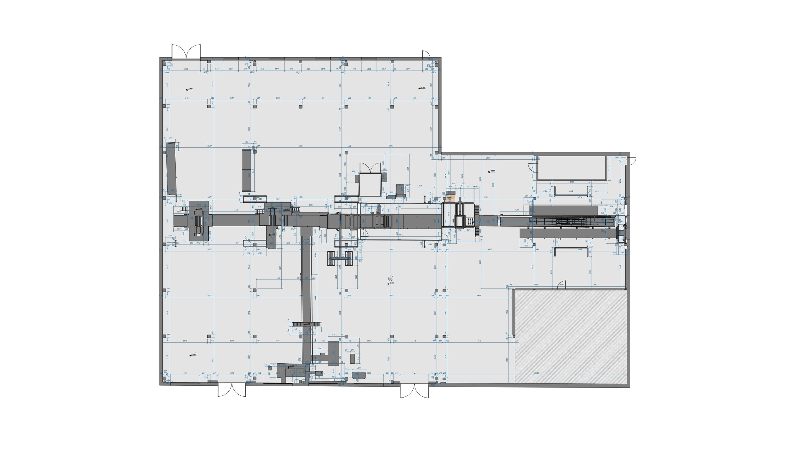
Outdoor electrical switchyards undergo equipment replacement, structural modifications, foundation reconstruction, and other changes throughout their operational life. As a result, original design drawings may no longer represent the actual arrangement of installed equipment and supporting infrastructure. This creates uncertainty when planning further modernization or preparing technical documentation.
ScanM2 provides As-Built Drawings Services for Open-Type Switchgears, preparing measured CAD documentation of existing outdoor high-voltage installations. Using available survey data, registered point clouds, and verified project information, we develop plans, elevations, sections, and equipment arrangement drawings that reflect the documented physical configuration of the facility.
Our drafting workflows help engineering teams replace uncertain geometric references with organized technical drawings suitable for reconstruction planning, equipment arrangement studies, and further design development.
Contact Us Now for a Free Consultation!
When Existing Switchyard Drawings No Longer Match Reality
Electrical substations and outdoor switchyards may remain in operation for decades. During that time, individual circuit breakers, disconnectors, transformers, support frames, and foundations can be replaced or modified without a complete update of the original drawing package.
Historical documentation may therefore contain outdated equipment dimensions, incorrect foundation positions, or structural arrangements that differ from the installation currently on site.
These discrepancies become especially important when new equipment must fit within an existing bay or when reconstruction work involves several engineering disciplines.
Measured as-built drawings provide a geometric reference for the visible and accessible parts of the facility. They can document the actual positions of selected structures and equipment while identifying areas where further verification is required.
A Drawing Package Organized Around Engineering Tasks
Not every switchyard modernization project requires the same documentation. The drawing package should be defined according to the intended engineering use, the available source measurements, and the elements that must be represented.
For example, an equipment replacement project may require detailed foundation and mounting layouts, while a broader reconstruction project may need coordinated general arrangement plans, elevations, and structural drawings.
General Arrangement Plans
General arrangement drawings show the horizontal organization of equipment bays, major structures, foundations, and selected infrastructure. Depending on the scope, they may include equipment footprints, steel support locations, access areas, and relevant dimensions.
These plans help engineers understand how individual components are positioned within the switchyard and how proposed modifications may affect surrounding installations.
Elevations of Equipment Bays and Steel Gantries
Elevation drawings document the visible vertical arrangement of structural supports and equipment. They may show portal heights, support levels, equipment envelopes, and other measurable features relevant to reconstruction planning.
For large outdoor installations, elevations can be prepared for selected equipment rows, structural frames, or individual bays rather than attempting to represent the entire facility in one drawing.
Sections Through Critical Areas
Section drawings provide additional information about the relative positions of equipment, structural elements, foundations, and accessible infrastructure at selected locations.
Sections may be particularly useful where the project involves equipment replacement, foundation modifications, or coordination between structural and electrical components.
Foundation and Equipment Support Layouts
Foundation drawings can document accessible concrete surfaces, pedestal positions, support footprints, and relevant mounting geometry where sufficient measurements are available.
These drawings support the assessment of existing installation arrangements, but they cannot establish concealed foundation dimensions, reinforcement, or structural capacity without additional information.
What Information Can Be Documented?
The level of detail depends on survey coverage, visibility, and the required drawing scale. A measured drawing should distinguish geometry that has been verified from information obtained through historical documentation or engineering assumptions.
| Facility element | As-built drawing information |
|---|---|
| Circuit breakers and disconnectors | Equipment footprints, external envelopes, accessible mounting positions |
| Instrument transformers and surge arresters | Visible equipment positions and supporting structures |
| Steel gantries and portals | Structural arrangement, measurable elevations and member positions |
| Concrete foundations | Accessible outlines, top elevations, pedestals and support locations |
| Busbar support structures | Visible supporting geometry and relative equipment arrangement |
| Cable trenches and channels | Accessible outlines, openings and visible structural features |
| Site infrastructure | Selected access routes, fences, technical areas and surface elements |
Electrical equipment ratings, conductor properties, concealed cable routes, and other non-geometric characteristics must be obtained from verified technical records or separate investigations.
From 3D Survey Data to 2D CAD Documentation
Preparing as-built drawings from laser scanning data involves interpreting three-dimensional measurements and translating relevant geometry into clear, dimensioned technical views.
The process begins with reviewing the available source information and defining which parts of the installation must be represented.
Where the project requires new measurements, 3D Laser Scanning Services for Open-Type Switchgears can provide spatial data for accessible structures and equipment.
Registered point clouds are then examined to identify the geometry needed for each drawing. Plan views, elevations, and sections can be developed using appropriate CAD workflows.
Before drafting begins, source datasets may require registration verification, cleaning, and organization through Point Cloud Processing Services for Open-Type Switchgears.
The resulting drawings should preserve the agreed coordinate references, drawing conventions, and dimensional requirements.
Documenting Equipment Bays for Modernization
Individual equipment bays are often the focus of switchyard reconstruction. A modernization project may involve replacing apparatus within an existing bay while retaining surrounding structures and infrastructure.
In this situation, the drawing package may need to show the relative positions of existing equipment, adjacent supports, foundations, and other relevant physical constraints.
For example, replacing a circuit breaker may require verification of the existing foundation footprint and the geometric relationship between the apparatus, its support structure, and neighboring installations.
Measured drawings can provide this information where the relevant geometry is accessible and sufficiently captured.
However, final installation dimensions and electrical clearances must be checked against the approved equipment documentation and applicable engineering requirements. As-built drawings alone do not certify that an arrangement is electrically compliant.
Comparing Existing Geometry with Historical Drawings
One important application of measured as-built documentation is identifying differences between the current installation and the original design records.
Where historical CAD drawings are available, their geometry can be compared with registered survey measurements using an agreed coordinate framework.
Potential differences may include displaced equipment supports, modified foundation footprints, changes in structural arrangements, or equipment installed in positions that differ from the original drawings.
Such comparisons can help engineering teams determine which parts of the documentation require revision before further design work begins.
Care must be taken when comparing datasets created using different coordinate systems, measurement methods, or reference points. Apparent discrepancies may result from alignment errors rather than actual physical changes.
Drawing Accuracy and Dimensional Reliability
The required accuracy of as-built drawings depends on their intended use. General arrangement plans may have different tolerance requirements from drawings prepared for equipment mounting or detailed structural interfaces.
Accuracy should therefore be defined before the measurement and drafting work begins.
Several factors influence the reliability of the final documentation:
- Quality and completeness of the original survey measurements.
- Consistency of survey control and coordinate references.
- Registration quality of the source point clouds.
- Visibility and accessibility of the measured elements.
- Drawing scale, dimensional tolerances, and drafting conventions.
- Verification of critical equipment and structural interfaces.
When highly precise mounting dimensions are required, supplementary field measurements or specialized metrology may be necessary. Point cloud data should not be assumed to meet every dimensional requirement without verification.
Working with Inaccessible and Concealed Elements
Outdoor switchyards can contain equipment and infrastructure that cannot be measured directly due to operational restrictions, limited visibility, or physical obstructions.
Examples include concealed foundation sections, buried cable routes, internal equipment components, and structural connections hidden behind installed apparatus.
These elements cannot be reliably reconstructed from visible surface measurements alone.
Where reliable historical drawings or verified technical records are available, they may be used as supplementary sources. Otherwise, the drawing package should identify the information gap rather than presenting assumed geometry as a confirmed measurement.
Surveying near energized electrical equipment must also comply with the facility operator’s access restrictions and approved safety procedures.
CAD Standards, Layers and Drawing Organization
A technically useful drawing package must be easy for engineers to interpret, update, and integrate into existing project documentation.
Depending on the client’s requirements, CAD files can be organized using defined layers, object categories, line types, annotation conventions, and drawing references.
Electrical equipment, steel structures, foundations, dimensions, and other relevant elements may be separated into logical drawing layers.
This organization allows project teams to review specific information without losing the overall arrangement of the switchyard.
Drawing templates, title blocks, revision conventions, and coordinate systems should be agreed as part of the project requirements.
As-Built Drawings and BIM: Choosing the Right Deliverable
Not every project requires a complete BIM model. For certain reconstruction tasks, a well-organized set of measured 2D drawings may provide the information needed for engineering review and design development.
As-built CAD drawings are particularly useful when the project requires specific plans, elevations, sections, and dimensional references.
Where a coordinated three-dimensional representation is required, Scan to BIM Services for Open-Type Switchgears can reconstruct existing installation geometry as structured model elements.
For modernization projects involving proposed equipment arrangements and multidisciplinary design coordination, BIM Modeling Services for Open-Type Switchgears can provide an additional digital engineering workflow.
The appropriate deliverable depends on the engineering objectives, software environment, available source information, and required documentation detail.
Deliverable Formats for Switchyard As-Built Documentation
Drawing deliverables can be prepared according to the agreed project specifications and software compatibility requirements.
- DWG: editable CAD drawings for engineering review and further design work.
- DXF: drawing exchange with compatible CAD applications.
- PDF: fixed-layout technical drawings for review and distribution.
- Registered point clouds: supporting measurement data where included in the project scope.
- Drawing registers: organized lists of sheets, drawing identifiers, and revision information where required.
For selected equipment components requiring detailed geometric reconstruction beyond conventional as-built drafting, Reverse Engineering Services for Open-Type Switchgears may be considered.
Quality Checks Before Drawing Delivery
Before final delivery, the drawing package should be reviewed against the agreed technical requirements and available source information.
Quality checks may include verifying coordinate consistency, reviewing dimensions, confirming the organization of drawing layers, and comparing selected geometry with the source point cloud.
Particular attention should be given to areas where measurements are incomplete or where historical documentation has been used to supplement the survey data.
The final documentation should communicate its measurement basis, intended use, and relevant limitations clearly enough for subsequent engineering teams to understand.
Request As-Built Drawings for Your Outdoor Switchyard
Accurate documentation of existing switchyard geometry can provide a reliable starting point for equipment replacement, structural reconstruction, and future engineering work.
ScanM2 prepares measured CAD documentation for industrial and energy infrastructure projects, converting suitable survey information into organized technical drawings.
Contact our team to discuss your facility, available survey data, required drawing types, software formats, and documentation objectives.

