

Reverse Engineering for Open-type switchgears
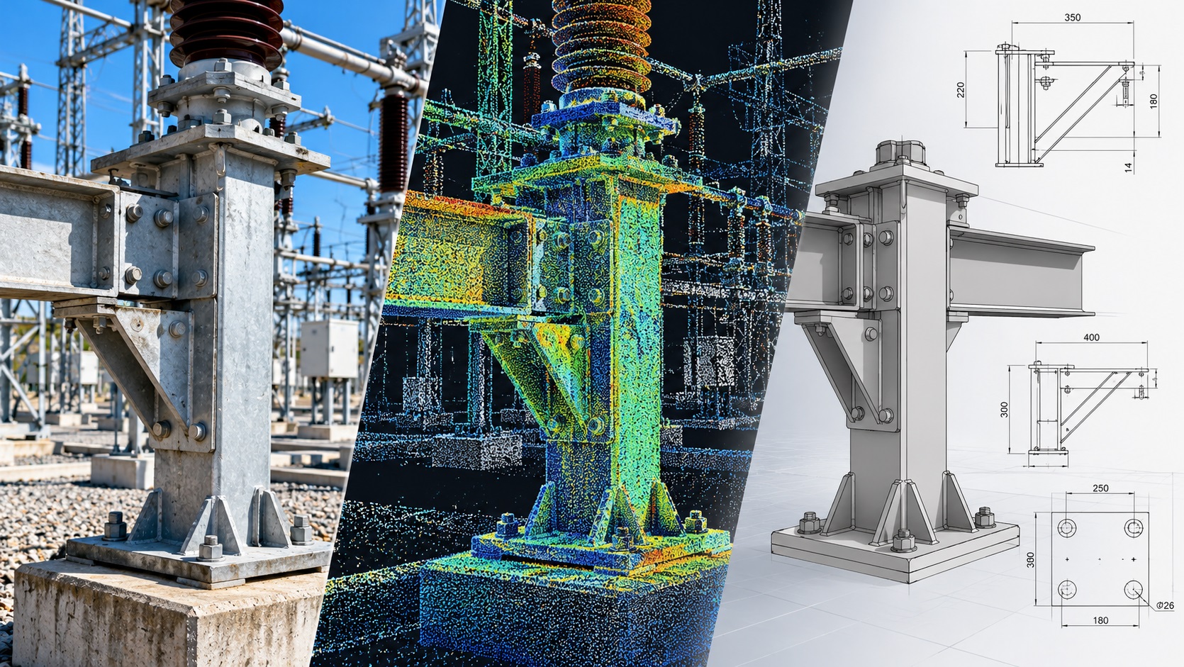
Outdoor high-voltage switchyards often contain equipment and supporting components that have remained in service for decades. During modernization, engineers may encounter obsolete mounting assemblies, undocumented steel supports, custom brackets, and mechanical interfaces for which original manufacturing drawings are unavailable. Replacing these elements can be difficult when their geometry must match an existing installation.
ScanM2 provides Reverse Engineering Services for Open-Type Switchgears, helping engineering teams reconstruct the geometry of existing components using 3D measurement data and CAD modeling. Our workflows support the development of digital representations of equipment supports, structural interfaces, mounting assemblies, and selected mechanical components for modernization and replacement planning.
Reverse engineering establishes a geometric reference for further engineering work. It does not independently confirm the material properties, electrical performance, mechanical strength, or suitability of a component for reuse or manufacture.
Contact Us Now for a Free Consultation!
When Original Component Drawings Are No Longer Available
Many existing switchyards have undergone several generations of equipment replacement and reconstruction. Individual components may have been modified, fabricated locally, or installed using project-specific mounting arrangements that are not fully documented.
When another modernization project begins, the engineering team may need to reproduce or adapt a component without access to its original manufacturing drawings.
Examples include custom steel brackets, equipment mounting plates, support frames, adapter assemblies, and mechanical connection elements.
Reverse engineering can help reconstruct their existing geometry from suitable measurements. The resulting CAD model may be used to develop technical drawings, evaluate geometric compatibility, or support the design of a replacement component.
The objective is not necessarily to reproduce an old component exactly. In some projects, engineers need an accurate representation of the existing interfaces so that a redesigned component can be developed around them.
Which Switchyard Components Can Be Reverse Engineered?
Reverse engineering is most useful for components whose geometry can be measured and whose intended engineering function is understood.
For outdoor switchyards, the potential scope may include selected mechanical and structural elements associated with electrical equipment installations.
| Component | Reverse engineering objective |
|---|---|
| Equipment mounting brackets | Reconstruct dimensions, hole patterns, and connection geometry |
| Steel support frames | Develop CAD geometry of existing members and interfaces |
| Adapter plates | Document existing mounting arrangements for replacement design |
| Mechanical linkage components | Reconstruct accessible geometry for engineering assessment |
| Equipment base assemblies | Measure support geometry and connection positions |
| Custom structural fittings | Prepare geometric models where original drawings are unavailable |
| Selected equipment housings | Document external geometry and relevant mechanical interfaces |
The suitability of a component for reverse engineering depends on its accessibility, measurement requirements, operating conditions, and the availability of supplementary technical information.
Safety-critical electrical components, insulation systems, and load-bearing assemblies require appropriate engineering verification before any reconstructed geometry is used for manufacturing or installation.
Reconstructing Equipment Mounting Interfaces
Equipment mounting interfaces are particularly important during the replacement of high-voltage apparatus. A new circuit breaker, disconnector, or instrument transformer may have a different mounting arrangement from the existing equipment.
In such cases, the engineering team may need to understand the geometry of existing supports, adapter plates, and accessible connection areas.
Reverse engineering can provide CAD representations of these interfaces based on suitable measurements.
Depending on the required precision, the process may involve terrestrial laser scanning, close-range scanning, direct dimensional measurements, or a combination of methods.
The resulting model can help engineers compare existing mounting geometry with the requirements of proposed replacement equipment.
Final interface dimensions, connection strength, installation tolerances, and equipment suitability must be verified through the relevant engineering design process.
From Physical Measurements to Parametric CAD Geometry
A scanned component is initially represented by measured points or surfaces. This geometric information must be interpreted before it can be converted into a useful engineering model.
Depending on the component, the reconstruction process may involve identifying reference planes, cylindrical features, mounting holes, structural profiles, and other geometric characteristics.
These features can then be represented through appropriate CAD modeling techniques.
For components with relatively simple geometry, the model may be constructed from measured dimensions and standard geometric features. More complex surfaces may require specialized reconstruction methods.
Where suitable, a parametric CAD model allows engineers to adjust dimensions, modify selected features, and develop alternative configurations without rebuilding the entire geometry.
However, the availability of a parametric model does not establish that the reconstructed component is suitable for manufacturing or service. Material selection, tolerances, loads, and other technical requirements must be determined separately.
As-Measured Geometry Versus Nominal Design Geometry
An existing component may no longer match its original design geometry. Wear, deformation, corrosion, manufacturing variation, and previous modifications can affect its measured dimensions.
This creates an important distinction between two possible reconstruction objectives.
As-Measured Reconstruction
An as-measured model represents the observed geometry of the existing component within the limitations of the measurement data.
This approach can be useful when documenting the current condition of a mounting assembly or evaluating the geometry of an existing installation interface.
Nominal Geometry Reconstruction
A nominal model attempts to represent the intended engineering geometry rather than every measured irregularity.
Developing nominal geometry may require identifying standard profiles, symmetry, design intent, and available manufacturing information.
Where the original design cannot be established reliably, assumptions must be documented and reviewed by the responsible engineers.
The distinction is especially important when a reconstructed component will be used as the basis for a replacement part.
Working with Worn, Corroded or Modified Components
Outdoor electrical installations are exposed to changing weather conditions throughout their service life. Steel fittings and mechanical assemblies may show corrosion, surface deterioration, or geometric changes.
Reverse engineering can document accessible surface geometry, but measurements alone cannot determine whether a component remains structurally or mechanically suitable for operation.
For example, surface scanning may reveal visible deformation of a support bracket, while concealed cracks, internal corrosion, and material degradation remain undetected.
Where component condition affects engineering decisions, appropriate inspection and testing methods must be used in addition to geometric reconstruction.
When a replacement part is being developed, the engineering team must determine whether the original geometry should be reproduced, corrected, or redesigned.
Measurement Methods for Different Component Sizes
Not all switchyard components can be measured effectively using the same equipment.
Large support structures and equipment assemblies may be documented using terrestrial laser scanning, while small mounting features and precision interfaces may require close-range scanning or direct metrology.
Measurement planning should consider component dimensions, accessibility, surface properties, required tolerances, and the intended use of the reconstructed model.
For larger installation geometry, 3D Laser Scanning Services for Open-Type Switchgears can provide a spatial reference for accessible equipment and structures.
Where point cloud datasets require registration, filtering, or optimization, Point Cloud Processing Services for Open-Type Switchgears can support preparation of the source geometry.
Precision requirements should be established before measurement begins. A general facility scan may not provide sufficient detail for reconstructing small holes, threads, contact surfaces, or other critical mechanical features.
Reverse Engineering Without Removing Equipment
Some components can be measured in their installed position, provided that access is authorized and the required surfaces are visible.
This approach may be useful when documenting large support frames or accessible mounting arrangements that would be difficult to remove.
However, installed components often contain hidden interfaces and surfaces that cannot be measured from the available scanner positions.
Where critical geometry is concealed, additional documentation, authorized disassembly, or direct inspection may be required.
Measurements near energized electrical equipment must follow the facility operator’s safety procedures and approved access conditions. Non-contact scanning does not remove electrical hazards or permit unrestricted access.
Using Reverse-Engineered Models in Modernization Projects
Reverse-engineered component models can support a wider engineering workflow when integrated with the existing switchyard geometry.
For example, a reconstructed mounting bracket may be reviewed in relation to an existing support frame and the proposed replacement equipment.
Where a digital model of the surrounding installation is available, component geometry can be coordinated with the broader project environment.
Scan to BIM Services for Open-Type Switchgears can provide an existing-condition model of selected structures and equipment arrangements.
For projects involving proposed reconstruction work, BIM Modeling Services for Open-Type Switchgears can support coordination of new and existing elements.
Reverse engineering and BIM modeling serve different purposes. Reverse engineering focuses on reconstructing selected component geometry, while BIM provides a structured environment for organizing and coordinating facility elements.
Verification Before Manufacturing or Installation
A reverse-engineered CAD model should be reviewed against the intended engineering requirements before it is used to develop manufacturing documentation.
The verification process may include geometric comparison with the source measurements, review of critical dimensions, confirmation of interface locations, and assessment of modeling assumptions.
Where the component performs a structural or safety-related function, additional engineering checks are essential.
These may include material identification, mechanical calculations, inspection requirements, manufacturing tolerances, and compliance with applicable technical standards.
For components associated with high-voltage equipment, compatibility with the original apparatus and manufacturer requirements must also be assessed by qualified specialists.
Reverse engineering provides geometric information for these decisions but does not replace the engineering approval process.
CAD Models, Technical Drawings and Deliverables
The final deliverables depend on the component geometry, intended engineering use, and required software compatibility.
- 3D CAD models: reconstructed component geometry prepared in agreed editable or exchange formats.
- STEP files: neutral CAD geometry for compatible engineering applications.
- IGES files: surface and geometry exchange where appropriate.
- DWG or DXF drawings: selected technical views and dimensions where included in the project scope.
- Reference point clouds or meshes: source geometry for review and verification.
- Measurement and modeling notes: information about relevant assumptions, limitations, and verification requirements.
Where the project requires broader documentation of existing equipment arrangements and structures, As-Built Drawings Services for Open-Type Switchgears can complement component-level reconstruction.
A Practical Workflow for Component Reconstruction
Each reverse engineering project begins with identifying the component, understanding its intended use, and defining which geometric features must be reconstructed.
The work may then proceed through several stages:
- Component assessment: review the available drawings, photographs, measurements, and technical requirements.
- Measurement planning: select appropriate scanning or metrology methods based on component size and required precision.
- Geometry capture: collect accessible surface and interface measurements under approved conditions.
- Data preparation: register, clean, and organize the measurement data as required.
- CAD reconstruction: develop the agreed geometric representation of the component.
- Geometric verification: compare relevant model features with the source measurements.
- Engineering handover: provide the agreed CAD files, technical views, and documented limitations.
Additional engineering validation, detailed design, or manufacturing preparation may be required depending on the component and its intended application.
Reverse Engineering for Existing Outdoor Switchyards
When original component drawings are missing or existing mounting arrangements have been modified, accurate geometric reconstruction can provide a useful starting point for modernization.
ScanM2 supports reverse engineering workflows for industrial and energy infrastructure, helping engineering teams transform suitable measurements into organized CAD geometry.
Contact our team to discuss the component type, available source information, required measurement accuracy, expected CAD deliverables, and intended engineering application.

