

Scan to BIM for Open-type switchgears
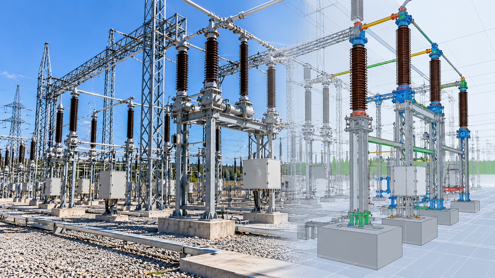
Outdoor switchyards are complex engineering environments where electrical equipment, steel gantries, foundations, cable infrastructure, and supporting structures must work within a coordinated spatial arrangement. When an existing switchyard is scheduled for modernization, outdated drawings and incomplete equipment records can make it difficult to understand the actual installation geometry.
ScanM2 provides Scan to BIM Services for Open-Type Switchgears, converting registered 3D laser scanning data into structured digital models of existing outdoor electrical installations. The resulting BIM models can support reconstruction planning, engineering coordination, equipment replacement studies, and the preparation of reliable as-built documentation.
Rather than treating a point cloud as a finished engineering deliverable, Scan to BIM transforms measured geometry into identifiable model elements that can be organized, reviewed, and incorporated into project workflows.
Contact Us Now for a Free Consultation!
From Millions of Measured Points to an Organized Switchyard Model
A registered point cloud contains spatial measurements of visible surfaces. It can represent the external geometry of equipment, structural supports, foundations, and other accessible objects, but the data does not automatically identify what those objects are or how they function.
Scan to BIM introduces an additional level of interpretation. Modelers use the point cloud, available technical documentation, and project-specific requirements to reconstruct selected elements as digital objects.
For outdoor switchgear facilities, this may involve modeling steel gantries, circuit breaker envelopes, disconnectors, instrument transformer supports, concrete foundations, equipment cabinets, cable channels, and surrounding site structures.
The objective is not to reproduce every measured point. It is to develop a useful digital representation of the existing installation at the agreed level of detail and geometric reliability.
What Makes Scan to BIM Different for Open-Type Switchgears?
Outdoor switchyards combine structural, civil, and electrical infrastructure within the same physical area. These disciplines are closely related spatially, but they require different modeling approaches.
A steel gantry may be reconstructed using structural members and connections. A concrete equipment foundation may be modeled as a civil or structural element. Electrical apparatus, however, often requires a simplified geometric representation supplemented by verified equipment information.
For example, a point cloud may capture the external dimensions and position of a circuit breaker, but it cannot establish its internal configuration, rated voltage, switching capacity, or operational characteristics.
These attributes must come from reliable engineering documentation rather than geometric measurements alone.
BIM Reconstruction by Equipment Bay
One practical approach to modeling a large outdoor switchyard is to divide the facility into equipment bays or functional zones. This makes it easier to organize the source measurements, coordinate model development, and review individual areas.
Depending on the installation, the model may be structured around incoming and outgoing line bays, busbar sections, transformer connections, coupling bays, and associated technical infrastructure.
Each zone can contain multiple categories of modeled elements:
- Electrical equipment: circuit breakers, disconnectors, instrument transformers, surge arresters, and other visible apparatus.
- Structural systems: steel portals, lattice structures, columns, beams, bracing, and equipment supports.
- Concrete structures: equipment foundations, support pedestals, accessible trenches, and cable channel structures.
- Site infrastructure: access routes, selected surface elements, fences, and relevant technical areas.
- Equipment interfaces: visible mounting locations and accessible geometric connections required for coordination.
Organizing the model by bay helps engineering teams isolate specific reconstruction areas without losing the spatial relationships across the wider installation.
Representing Electrical Equipment in Revit
Electrical switchyard equipment presents a particular modeling challenge. Individual devices may contain numerous insulators, operating mechanisms, support frames, and small components. Reproducing every visible detail is not always necessary for the intended engineering application.
For equipment arrangement studies, simplified model families may be sufficient to represent the measured position, orientation, overall dimensions, and relevant connection interfaces.
More detailed representations may be required when equipment replacement involves closely spaced structures, mounting interfaces, or other geometry-sensitive constraints.
Where verified manufacturer data is available, it may be incorporated into the model to improve equipment identification and support engineering review.
However, the geometric model must distinguish between information obtained from scanning, information taken from technical documentation, and assumptions introduced during reconstruction.
Steel Gantries and Supporting Structures
Steel portals and equipment support structures are among the most important elements in an outdoor switchyard BIM model. They establish the spatial framework for equipment arrangements and can influence reconstruction options.
Using the point cloud as a geometric reference, modelers can reconstruct accessible columns, beams, bracing systems, support frames, and selected connection areas.
Where the source data provides sufficient coverage, the model can reflect measured structural positions and deviations from an idealized arrangement.
For instance, the measured position of a gantry column may differ from its original design coordinates. Depending on the project tolerance requirements, that difference may need to be represented or documented.
The model does not replace structural calculations or condition assessments. Load-bearing capacity, corrosion, connection integrity, and other engineering properties require separate verification.
Modeling Foundations and Civil Infrastructure
Equipment replacement often depends on the existing foundation layout. A new apparatus may have different dimensions, support requirements, or mounting arrangements from the equipment currently installed.
Scan to BIM can reconstruct the visible geometry of concrete foundations, pedestals, equipment bases, and accessible cable channel structures.
This information can support preliminary assessment of available installation space and coordination with proposed equipment arrangements.
Nevertheless, laser scanning captures only visible and measurable surfaces. Underground foundation geometry, reinforcement, embedded components, and concealed cable routes cannot be reliably reconstructed from surface point cloud data alone.
Such elements should be modeled from verified drawings, additional investigations, or clearly identified assumptions where permitted by the project requirements.
Choosing the Right Level of Detail
The required level of detail should be established before BIM reconstruction begins. Excessive geometric detail can increase modeling time and file complexity without improving the intended engineering outcome.
For switchyard modernization, the appropriate level of detail depends on whether the model will be used for general spatial coordination, equipment layout development, foundation modification, or detailed interface studies.
| Modeling objective | Typical representation |
|---|---|
| General facility overview | Major structures, equipment envelopes, foundations, and overall spatial arrangement |
| Equipment replacement planning | Measured equipment positions, relevant mounting geometry, adjacent structures, and installation constraints |
| Structural reconstruction | Selected steel members, support geometry, and relevant structural interfaces |
| Detailed coordination | Project-defined geometry and attributes for elements involved in the proposed modifications |
LOD 300 or LOD 400 requirements may be considered for selected elements when appropriate, but the exact modeling scope must be agreed for each project. A higher LOD designation does not automatically establish that the existing-condition geometry has been independently verified.
Measured Geometry, Documented Information and Assumptions
A reliable existing-condition BIM model should communicate not only the geometry of an object but also the origin and limitations of the information used to create it.
Three information categories are especially relevant for outdoor switchgear reconstruction.
Geometry Confirmed by Point Cloud Measurements
Visible surfaces and accessible structures may be reconstructed from registered scan data within the agreed modeling tolerances. These elements can provide a measured spatial reference for engineering coordination.
Attributes Obtained from Technical Documentation
Equipment identifiers, manufacturer details, electrical ratings, and other non-geometric attributes may be incorporated when reliable project records are supplied.
Elements Requiring Additional Verification
Concealed foundations, inaccessible connection details, underground cable routes, and poorly captured equipment components may require additional measurements or documentation.
Keeping these information sources distinguishable helps reduce the risk of treating inferred model geometry as confirmed existing conditions.
How Scan to BIM Supports Switchyard Reconstruction
A BIM model developed from existing-condition measurements can serve as a common spatial reference for the engineering disciplines involved in switchyard modernization.
For example, an equipment replacement project may require the electrical design team to evaluate the proposed apparatus layout while structural engineers review supporting steelwork and civil engineers assess foundation modifications.
When the relevant existing elements are represented in a coordinated model, the project team can compare proposed geometry with the measured installation.
Potential spatial conflicts may be identified during model coordination, reducing dependence on incomplete historical drawings.
Importantly, BIM-based geometric coordination does not replace electrical clearance calculations, insulation coordination, equipment certification, or other required engineering checks.
Handling Large Point Clouds and Complex Model Files
Outdoor switchyards can generate substantial point cloud datasets, particularly when multiple equipment bays and surrounding infrastructure are captured.
Efficient BIM reconstruction requires a practical approach to file organization and model performance.
Source point clouds may be divided into logical survey areas, with separate model components developed for individual zones or disciplines. This allows relevant data to be loaded and reviewed without unnecessarily increasing the complexity of the entire project.
Prior to modeling, scan registration, cleaning, and data preparation may be completed through Point Cloud Processing Services for Open-Type Switchgears.
Where new measurements are required, our 3D Laser Scanning Services for Open-Type Switchgears can provide the source geometric data for the reconstruction workflow.
BIM Model Quality Control
Quality control is an essential part of Scan to BIM, particularly when the resulting model will be used to develop reconstruction designs.
The verification process may include comparing modeled surfaces with the registered point cloud, reviewing equipment positions, checking coordinate consistency, and identifying areas where the source measurements are incomplete.
Model review should focus on the geometry that matters for the intended engineering application rather than simply maximizing the number of modeled components.
Where tolerances are specified, deviations between the modeled geometry and measured surfaces can be evaluated against the agreed requirements.
Critical interfaces may still require additional field verification before construction or equipment installation.
Deliverables and Software Compatibility
Scan to BIM deliverables are determined by the intended project workflow, software environment, and information requirements.
- Autodesk Revit models (RVT): structured digital representations of selected existing switchyard elements.
- IFC files: model exchange for compatible multidisciplinary workflows, where required.
- Registered point clouds: source measurement data for geometric verification and future reference.
- Model views and schedules: project-defined information for reviewing modeled elements and their attributes.
- CAD documentation: selected plans, elevations, and sections where included in the agreed scope.
For projects requiring detailed technical plans and sections, the reconstructed model may also support As-Built Drawings Services for Open-Type Switchgears.
Where the project includes new equipment arrangements or coordinated design development, BIM Modeling Services for Open-Type Switchgears can address the next stage of the digital engineering workflow.
When Is Scan to BIM Particularly Useful?
Existing-condition BIM reconstruction is particularly relevant when the available drawings do not accurately represent the current installation or when several engineering disciplines need to work with the same spatial reference.
Typical applications include modernization of aging outdoor switchyards, replacement of major electrical apparatus, reconstruction of equipment foundations, modification of steel support structures, and preparation of coordinated digital facility documentation.
For individual components that require more detailed geometric reconstruction, Reverse Engineering Services for Open-Type Switchgears may be used as a complementary workflow.
Plan Your Open-Type Switchgear Scan to BIM Project
Creating a useful BIM model of an existing outdoor switchyard begins with defining the engineering purpose, available measurement data, required modeling scope, and expected deliverables.
ScanM2 supports the conversion of registered point clouds into structured digital models for industrial and energy infrastructure projects. Our team can assess the available source data, modeling requirements, software formats, and information needed for subsequent engineering work.
Contact us to discuss your switchyard configuration, reconstruction objectives, required model detail, and project documentation.

