

BIM Modeling for Open-type switchgears
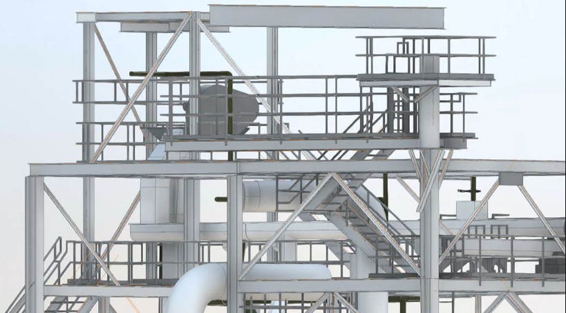
Modernizing an outdoor electrical switchyard involves coordinating much more than the installation of new electrical equipment. Circuit breakers, disconnectors, instrument transformers, steel gantries, equipment foundations, cable infrastructure, and access areas must fit within an existing facility while meeting project-specific engineering requirements.
ScanM2 provides BIM Modeling Services for Open-Type Switchgears, helping engineering teams develop coordinated digital models of outdoor high-voltage installations. Our BIM workflows support equipment arrangement studies, structural and civil coordination, reconstruction planning, and the integration of existing-condition geometry with proposed modifications.
A coordinated BIM environment allows project participants to review how electrical equipment, supporting structures, foundations, and associated infrastructure interact before construction or installation begins.
Contact Us Now for a Free Consultation!
BIM Modeling for the Reconstruction of Existing Switchyards
Outdoor switchyards are frequently modernized in stages. Existing equipment may remain in operation while selected bays are reconstructed, new apparatus is installed, or supporting infrastructure is modified.
These projects require careful coordination between the existing installation and proposed engineering solutions. A change to one equipment position may affect supporting steelwork, foundation geometry, cable routing, maintenance access, and adjacent structures.
BIM modeling provides a structured environment for developing and reviewing these relationships. Existing elements can be represented alongside proposed equipment and construction components, allowing engineers to examine the spatial implications of planned modifications.
The model can be organized by equipment bay, discipline, construction phase, or another agreed project structure, depending on the needs of the engineering team.
Coordinating Electrical, Structural and Civil Infrastructure
One of the main advantages of BIM modeling is the ability to coordinate different engineering disciplines within a shared spatial reference.
In an outdoor switchyard, electrical equipment arrangements are closely connected to structural supports and civil infrastructure. Even relatively small layout modifications can create additional requirements for foundations, steelwork, and adjacent technical systems.
Electrical Equipment Arrangements
The electrical portion of the model may include circuit breakers, disconnectors, instrument transformers, surge arresters, busbar support arrangements, equipment cabinets, and other project-relevant apparatus.
Equipment models can represent approved dimensions, installation positions, orientations, and geometric interfaces. Verified manufacturer information may be incorporated where available.
Structural Steelwork
Steel gantries, portals, columns, beams, bracing, and equipment support frames can be modeled to coordinate the structural arrangement with electrical equipment layouts.
Where detailed structural design information is available, the model may incorporate relevant member profiles, connection zones, and other specified geometry.
Foundations and Civil Works
Concrete foundations, equipment pedestals, accessible cable trenches, technical channels, and selected site infrastructure can be represented in the same project environment.
This allows civil and structural teams to coordinate proposed construction elements with the equipment arrangement and existing site constraints.
A Typical Equipment Replacement Scenario
Consider a modernization project involving the replacement of an existing high-voltage circuit breaker with a new model. The replacement equipment may have different overall dimensions, support positions, connection interfaces, or maintenance requirements.
Before the installation arrangement is finalized, the project team may need to examine several interdependent conditions:
- Whether the proposed equipment envelope fits within the available physical space.
- How the new mounting arrangement relates to existing foundations and support frames.
- Whether adjacent structural elements interfere with the proposed installation geometry.
- How maintenance access and equipment handling routes are affected.
- Which civil or structural modifications must be coordinated with the electrical design.
A coordinated BIM model helps visualize these relationships and identify potential geometric conflicts before installation work begins.
Electrical clearances, insulation coordination, equipment ratings, structural capacity, and operational safety must still be verified by the responsible engineering specialists. Geometric coordination alone does not establish compliance with electrical or structural design requirements.
Existing Conditions and Proposed Design in One Model
Reconstruction projects often begin with incomplete or outdated documentation. Existing foundations may differ from historical drawings, equipment may have been replaced, and steel support arrangements may have changed during previous modernization work.
Where suitable measured data is available, the existing facility can be reconstructed through Scan to BIM Services for Open-Type Switchgears.
The resulting existing-condition model can then be used as a reference for developing proposed equipment arrangements, structural modifications, and civil works.
It is important to maintain a clear distinction between measured existing elements and proposed design components. This distinction helps project participants understand which objects represent the current installation and which belong to the planned reconstruction.
For projects requiring new source measurements, 3D Laser Scanning Services for Open-Type Switchgears can provide geometric information about accessible structures and equipment.
Equipment Bay Modeling and Project Organization
Large switchyards may contain multiple line bays, transformer connections, busbar sections, coupling arrangements, and associated technical installations.
Organizing a BIM model around these functional areas can make the project easier to manage, particularly when reconstruction is planned in several stages.
Each equipment bay may be developed as a defined modeling zone containing the relevant electrical apparatus, support structures, foundations, and adjacent infrastructure.
This approach allows engineering teams to review individual work areas while retaining a coordinated view of the overall switchyard.
Model organization may also include equipment identifiers, discipline classifications, project phases, and other agreed information parameters.
Clash Detection and Spatial Coordination
Spatial conflicts between proposed equipment and surrounding structures can create installation difficulties and additional construction work.
BIM coordination enables project teams to examine geometric intersections and proximity relationships between modeled components.
Potential issues may include a proposed equipment support intersecting an existing foundation, a structural brace obstructing an installation envelope, or a new cable channel conflicting with another modeled civil element.
These conditions can be reviewed using suitable model coordination tools and project-defined checking rules.
Not every detected geometric intersection represents a design error, and not every engineering constraint can be identified through automatic clash detection.
For outdoor electrical installations, required electrical clearances and operational restrictions must be assessed using applicable engineering standards and verified equipment information, not merely the absence of model clashes.
Supporting Construction Phasing and Installation Planning
Modernization of operating switchyards may require construction activities to be divided into separate stages. Equipment replacement, foundation modifications, and structural installation can depend on the availability of specific work areas and approved operating conditions.
A BIM model can support visualization of the planned sequence by distinguishing existing, temporary, demolished, and proposed elements where the project scope requires this information.
For example, a reconstruction model may help illustrate which equipment foundations are retained, which structures are scheduled for removal, and where new apparatus is intended to be installed.
When integrated with an approved project schedule, model elements may also be used in construction sequencing workflows.
However, the BIM model does not independently authorize work near energized equipment or determine safe switching procedures. Such activities remain subject to the facility operator’s requirements and approved work plans.
Model Detail Based on Engineering Objectives
The required level of model detail depends on the purpose of the project. A general arrangement study may need accurate equipment envelopes and principal support structures, while detailed installation coordination may require additional geometric information.
Model development should therefore begin with a clear definition of the required elements, information attributes, and intended engineering applications.
| Project objective | BIM modeling focus |
|---|---|
| General arrangement planning | Equipment positions, major structures, foundations and overall spatial relationships |
| Equipment replacement | Proposed apparatus geometry, mounting interfaces and surrounding installation constraints |
| Structural modifications | Steel members, supporting frames and relevant connection geometry |
| Civil reconstruction | Foundations, pedestals, accessible cable infrastructure and proposed civil elements |
| Multidisciplinary coordination | Consistent model references, element classification and geometric conflict review |
| Construction planning | Existing, removed and proposed elements organized by project stage |
Project-defined LOD requirements, including LOD 300 or LOD 400 for selected components where appropriate, can help establish the expected modeling scope. The required information should be specified at the element level rather than assuming that all switchyard components need identical detail.
Information Management in Switchyard BIM Models
A BIM model can contain more than three-dimensional geometry. Depending on the available project information, individual elements may include equipment identifiers, classification parameters, installation zones, document references, and other agreed attributes.
For example, an equipment object may be linked to a verified manufacturer designation or an approved technical document. A structural element may include an assigned member profile or project classification.
These attributes can improve model navigation and support communication between engineering disciplines.
Information should be traceable to an appropriate source. Electrical characteristics, structural properties, and equipment performance data must not be inferred from visual geometry when reliable documentation is unavailable.
Model Coordination with Point Cloud Data
For existing switchyards, registered point clouds can provide a valuable geometric reference during BIM model development.
Modelers may use the point cloud to check the relative positions of existing structures, foundations, and equipment before proposed modifications are introduced.
Where large outdoor areas are involved, coordinate consistency becomes especially important. The project team should establish an agreed reference system and verify that existing-condition data and proposed design models use compatible coordinates.
Source data preparation, registration and optimization may be performed through Point Cloud Processing Services for Open-Type Switchgears.
Incomplete measurements, inaccessible equipment areas, and other source limitations should be identified so that model users do not mistake unverified geometry for confirmed existing conditions.
BIM Quality Assurance Before Engineering Handover
A coordinated switchyard model must be suitable for its intended engineering application. Quality assurance therefore involves more than confirming that the model opens correctly in the selected software.
Depending on the agreed project requirements, model review may address:
- Consistency of project coordinates and reference levels.
- Correct organization of equipment bays and technical areas.
- Appropriate classification of electrical, structural and civil elements.
- Geometric consistency with supplied drawings and measured source data.
- Identification of missing or unverified model information.
- Review of relevant geometric conflicts between coordinated disciplines.
- Compliance with the agreed model structure, naming conventions and delivery formats.
The review criteria should reflect the intended use of the model. Equipment installation interfaces may require more detailed verification than areas represented for general project context.
BIM Deliverables for Outdoor Switchyard Projects
Deliverables are defined according to the project scope, engineering software, and required information exchange procedures.
Typical deliverables may include coordinated Autodesk Revit models, IFC exchange files, discipline-specific model components, project-defined equipment information, and selected model views for engineering review.
Where required, BIM models can also support the preparation of plans, elevations, and sections. Dedicated As-Built Drawings Services for Open-Type Switchgears can address measured technical documentation of existing installations.
For specialized components requiring detailed geometric reconstruction, Reverse Engineering Services for Open-Type Switchgears may complement the broader BIM workflow.
Develop a Coordinated BIM Model for Your Switchyard
Effective BIM modeling for outdoor electrical switchyards begins with a clear understanding of the reconstruction scope, engineering disciplines, available source information, and required model outputs.
ScanM2 supports digital modeling workflows for industrial and energy infrastructure, helping project teams organize existing-condition information and coordinate proposed modifications within a structured three-dimensional environment.
Contact our team to discuss your outdoor switchyard project, required model detail, software compatibility, and engineering documentation needs.

